


Part Number: ADS131E08S
Other Parts Discussed in Thread: ADS131E08
Hi,
I am using ADS131E08S for 50Hz AC measurement.
ADC is used in bipoler mode (+2.5 to -2.5)
DRDY is connected to interrupt pin of micro-controller.
START pin in connected to GPIO pin of micro-controller.
ADC is running in internal clock mode.
ADC init sequence.
1. RESET command send over SPI
2. SDATAC command, stop continuos mode
3. Reading ADC ID register on SPI 0x20 0x00 0x00 ( Reading Id as 0xD2)
4. Send below configuration using WREG command
CONFIG1 = 0xD6 // Multiple data readback mode, Data Rate 1 KSPS
CONFIG2 = 0xE0 // Test signals are driven externally
CONFIG3 = 0xE0 // VREFP is set to 4 V
FAULT = 0x00 // 95% to 5 %
CHnSET = 0x10 // Gain 1, Nomral input
5. ADC offset calibration command
6. ADC Read continuos mode command
Once init is completed, I am making START pin high, which will be held high forever. On DRDY i am getting interrupts and storing the samples by reading 27 bytes over SPI.
Some time samples are getting missed, kindly refer the below plotted sine wave based on the samples from ADC.
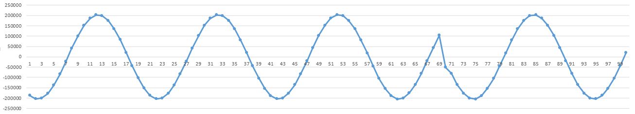
What am i doing wrong? any suggestion.
Thanks
Jignesh Gohil

