Other Parts Discussed in Thread: ADS1292
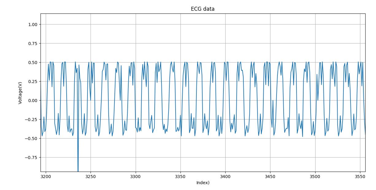
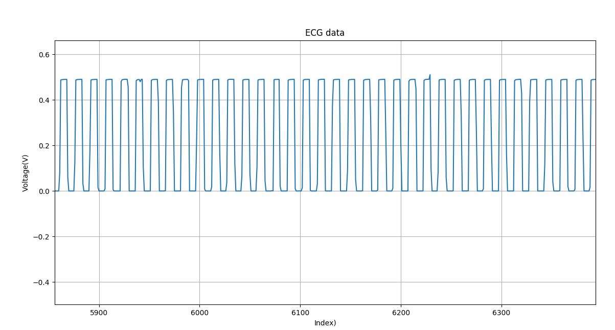
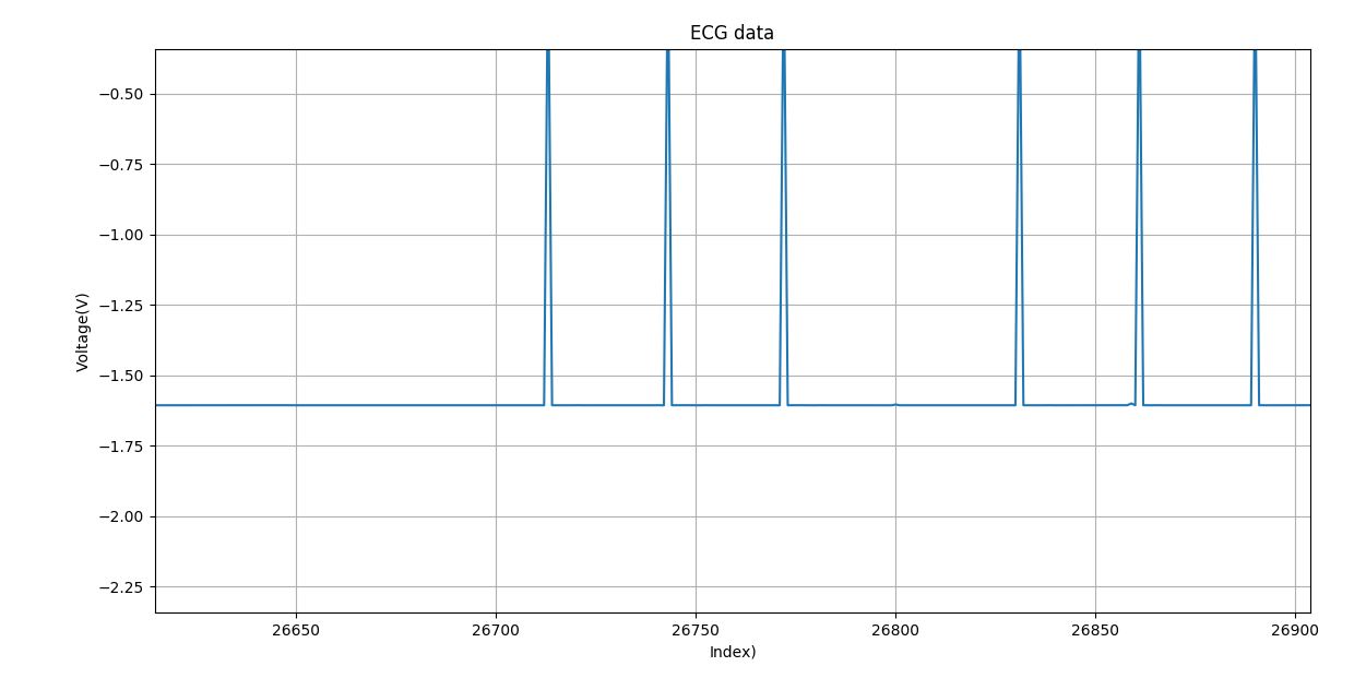
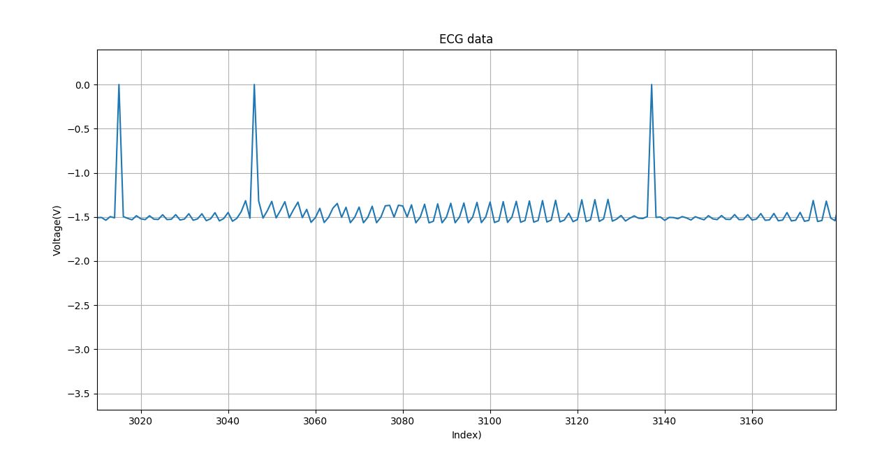
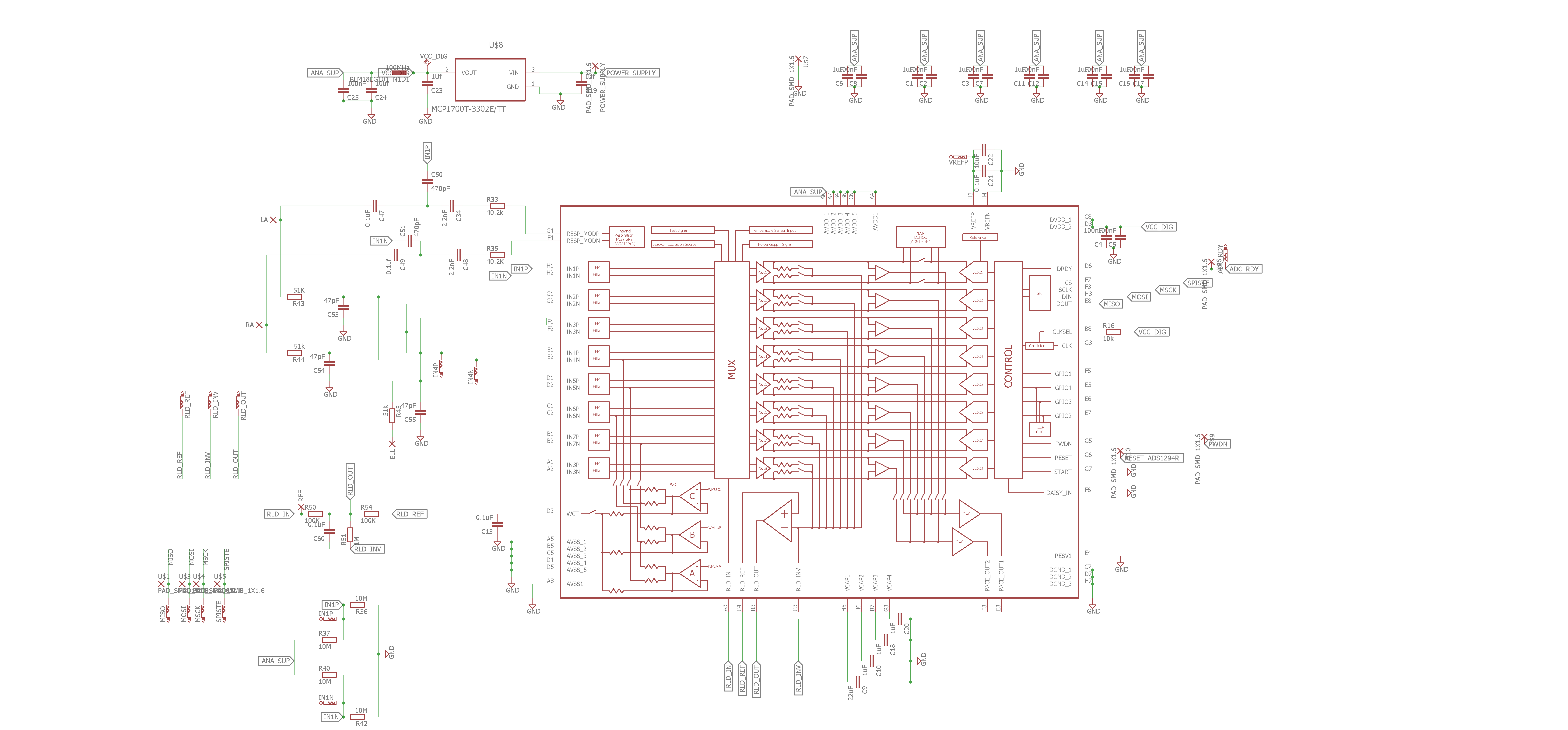
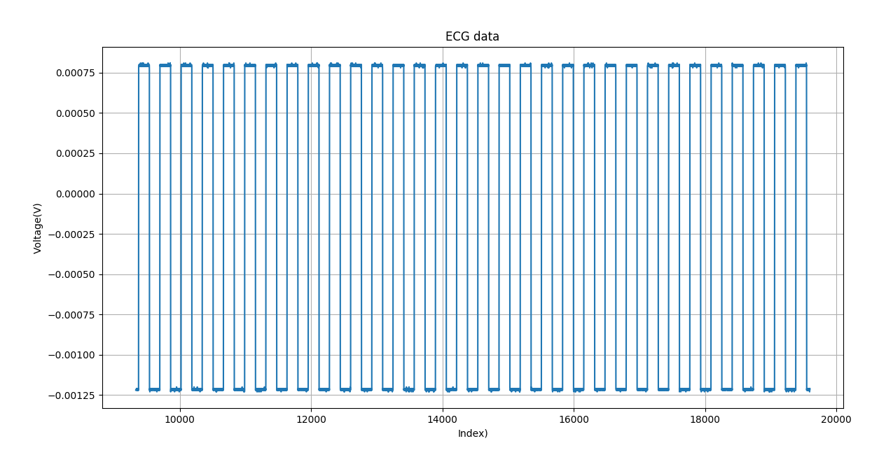
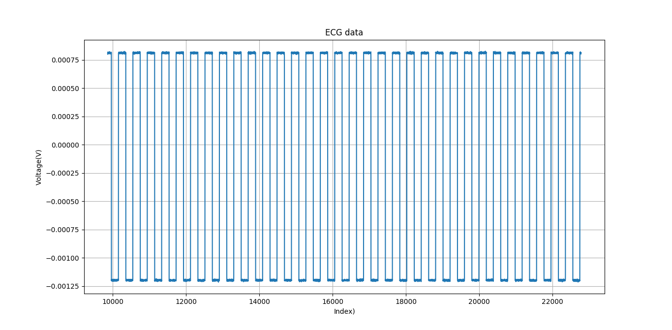
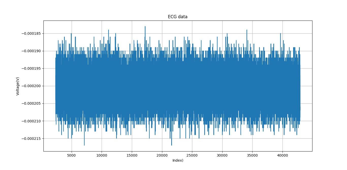
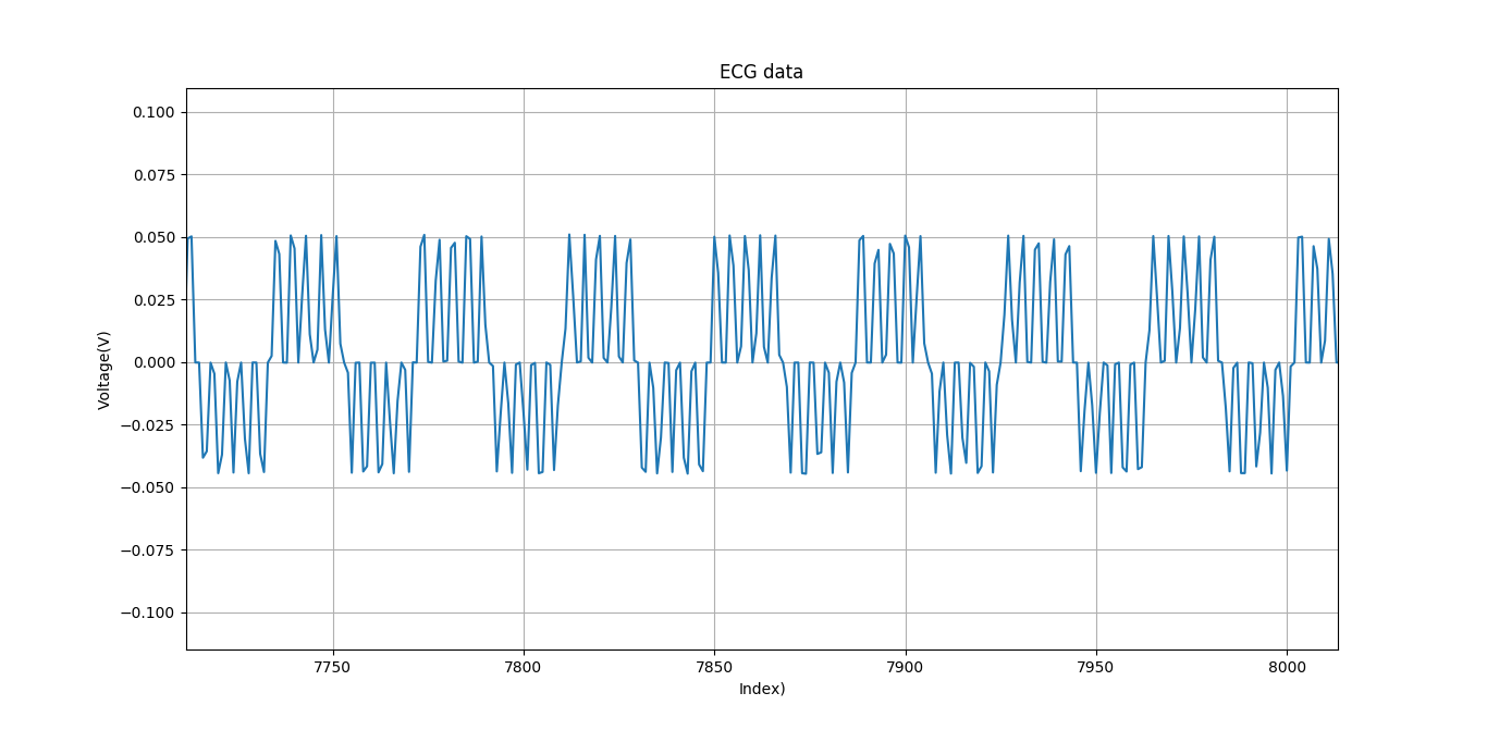
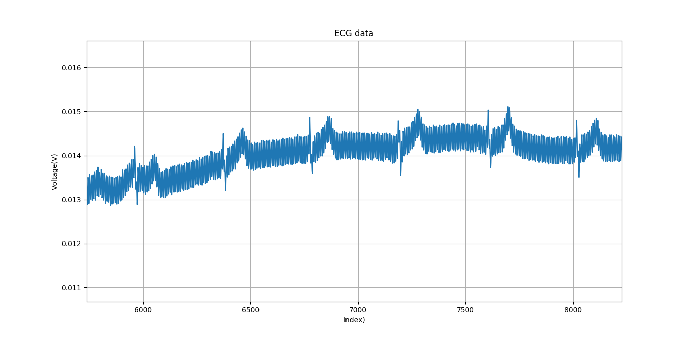
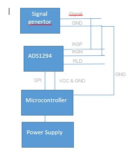
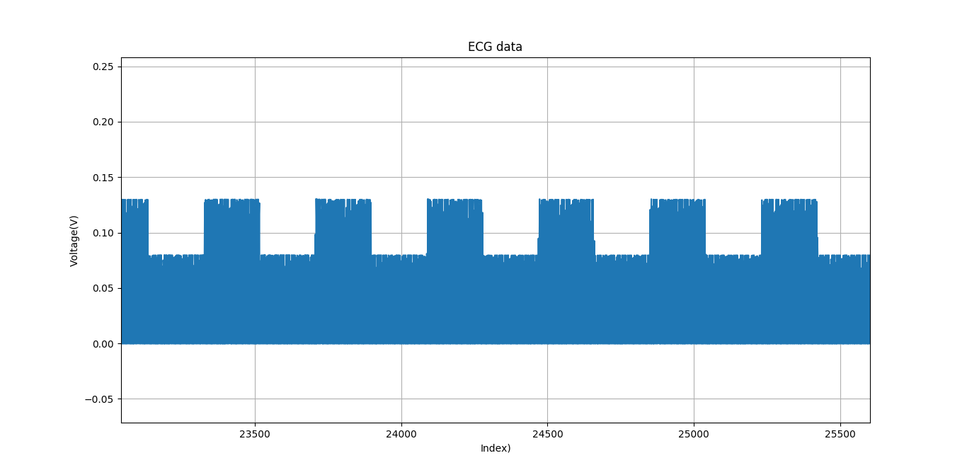
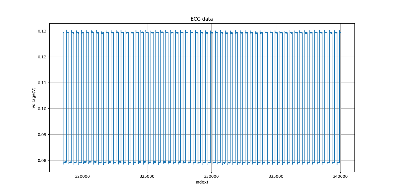
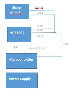
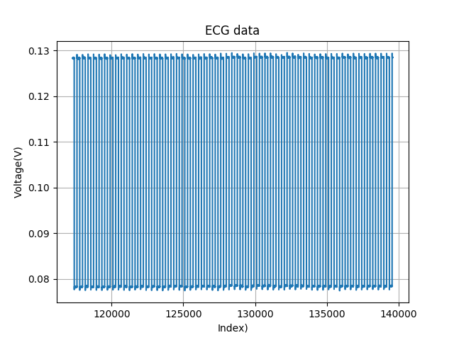
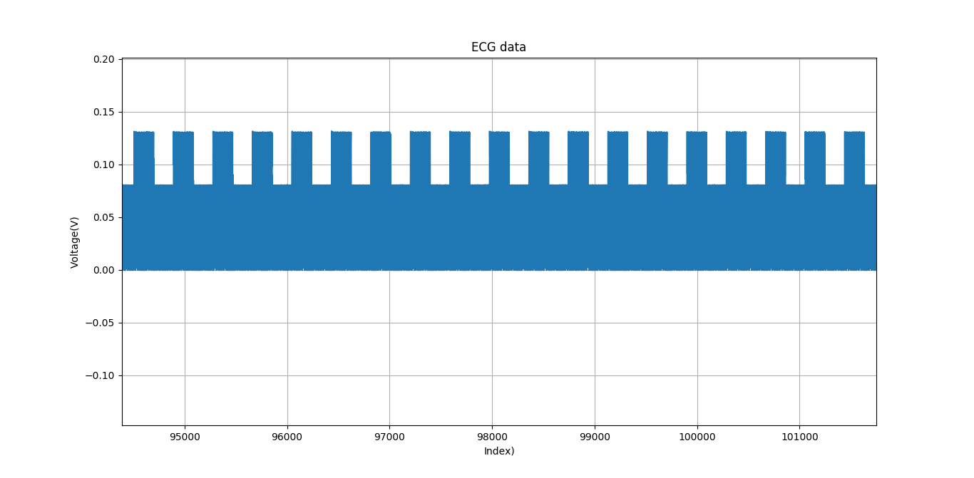
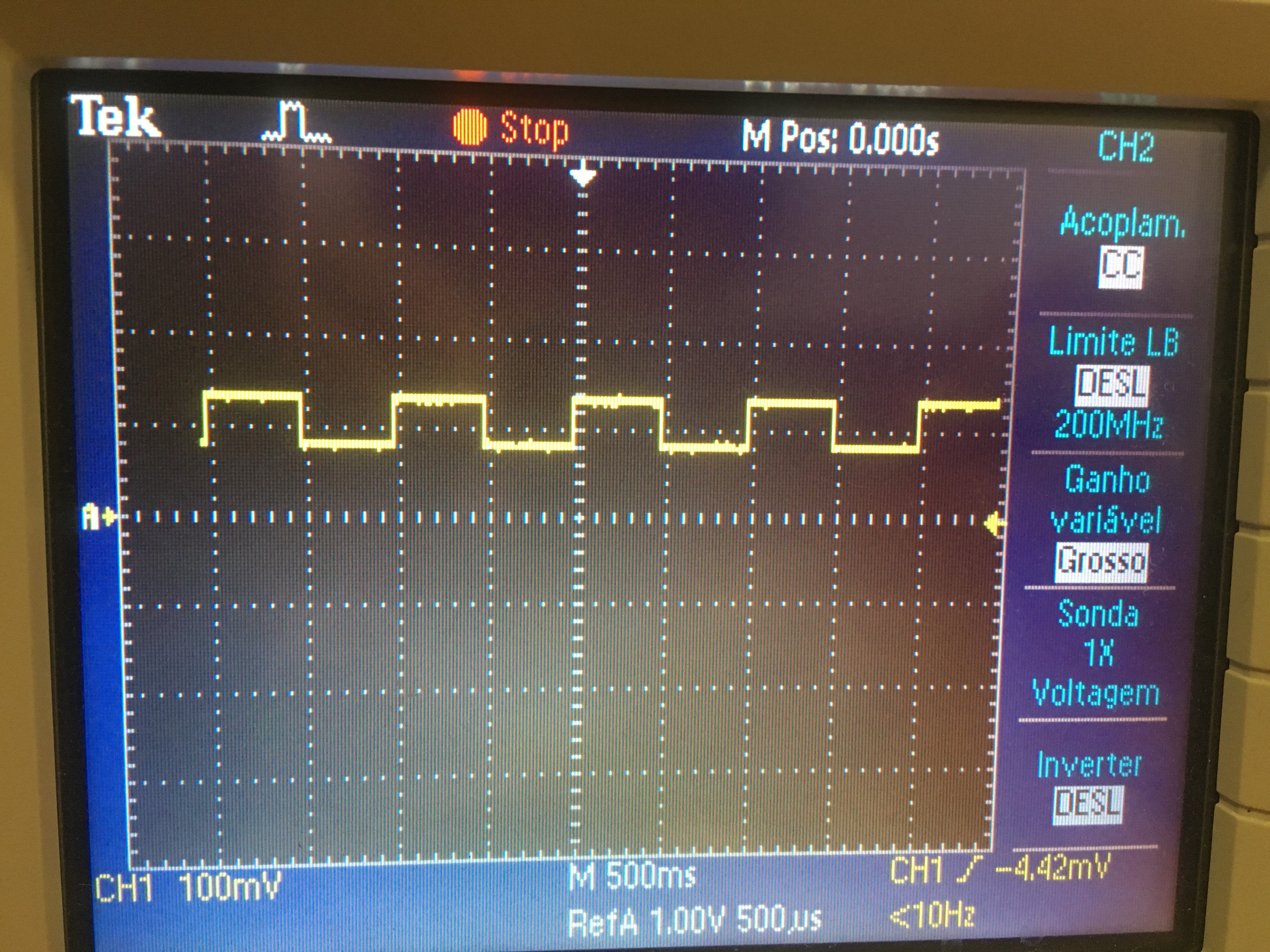
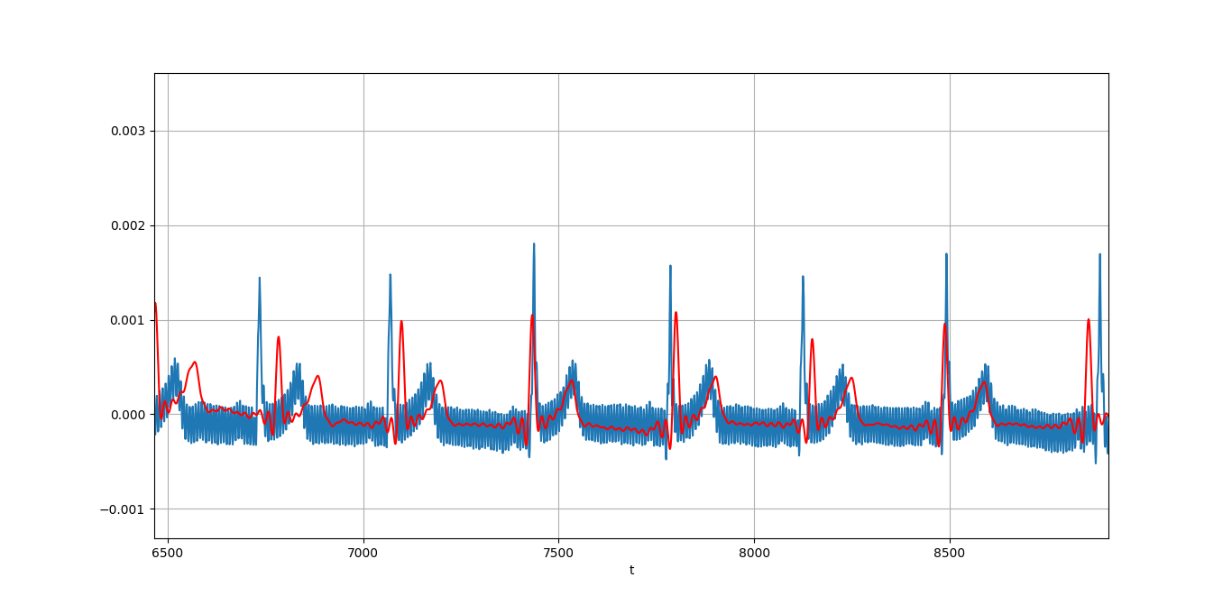
Hi, everyone, i configure the ads1294R in test mode, where i can see the wave of the signal generated by the ads.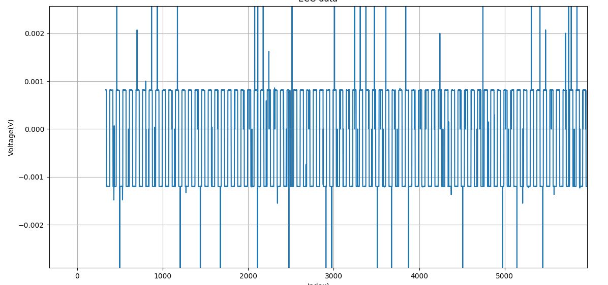
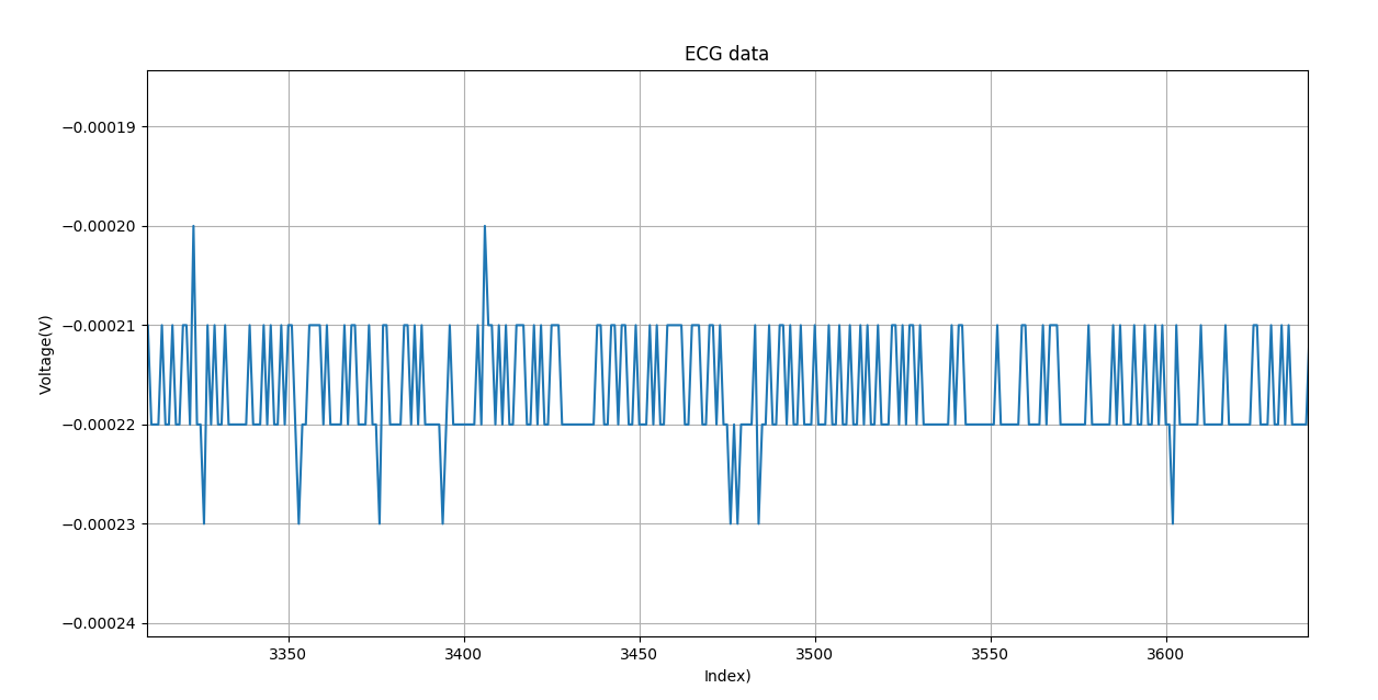
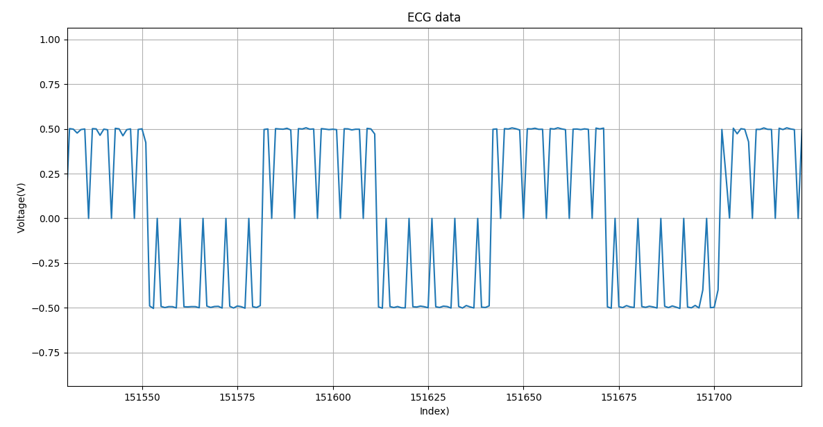
But if you see the chart with test wave i have some points that are out of range, they do not seem to me to be noise, but another problem, like a bad SPI configuration or read from ads1294R. Any suggestions what can be this problem? This chart is made without any digital filter or average! Yes i know that is possble clean some of this that but i thinks that is some wrong...
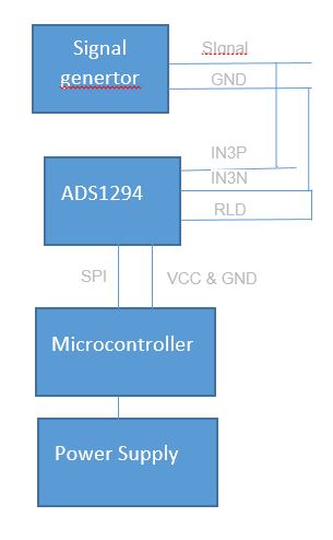
Below is possible to see the configuration registers:
ads1292_drv.reg[ADS1292_REG_CONFIG1] = 0<<BIT7 | 1<<BIT6 | 0<<BIT5 | 0<<BIT4 | 0<<BIT3 | 1<<BIT_REV_DR2 | 1<<BIT_REV_DR1 | 0<<BIT_REV_DR0;
ads1292_drv.reg[ADS1292_REG_CONFIG2] = 0<<BIT7 | 0<<BIT6 | 1<<BIT5 | 1<<BIT4 | 1<<BIT3 | 0<<BIT2 | 0<<BIT1 | 0<<BIT0;
ads1292_drv.reg[ADS1292_REG_CONFIG3] = 1<<BIT7 | 1<<BIT6 | 0<<BIT5 | 0<<BIT4 | 1<<BIT3 | 1<<BIT2 | 0<<BIT1 | 0<<BIT0;
ads1292_drv.reg[ADS1292_REG_CH1SET] = 1<<BIT_PD1 | 0<<BIT_GAIN1_2 | 0<<BIT_GAIN1_1 | 0<<BIT_GAIN1_0 | 0<<BIT3 | 0<<BIT_MUX1_2 | 0<<BIT_MUX1_1 | 0<<BIT_MUX1_0;
ads1292_drv.reg[ADS1292_REG_CH2SET] = 0<<BIT_PD2 | 0<<BIT_GAIN2_2 | 0<<BIT_GAIN2_1 | 1<<BIT_GAIN2_0 | 0<<BIT3 | 1<<BIT_MUX2_2 | 0<<BIT_MUX2_1 | 1<<BIT_MUX2_0;
ads1292_drv.reg[ADS1292_REG_CH3SET] = 1<<BIT_PD1 | 0<<BIT_GAIN1_2 | 0<<BIT_GAIN1_1 | 1<<BIT_GAIN1_0 | 0<<BIT3 | 0<<BIT_MUX1_2 | 0<<BIT_MUX1_1 | 0<<BIT_MUX1_0;
ads1292_drv.reg[ADS1292_REG_CH4SET] = 1<<BIT_PD2 | 0<<BIT_GAIN2_2 | 0<<BIT_GAIN2_1 | 1<<BIT_GAIN2_0 | 0<<BIT3 | 0<<BIT_MUX2_2 | 0<<BIT_MUX2_1 | 0<<BIT_MUX2_0;
SPI mode 1
SPI Speed 512000
I will wait for your opinion,best regards,
Jaime Lopes