This thread has been locked.

If you have a related question, please click the "Ask a related question" button in the top right corner. The newly created question will be automatically linked to this question.

ADS124S08: DRDY never goes low even when all the conditions are good

Part Number: ADS124S08
Other Parts Discussed in Thread: ADS1248

Hi Forum,

We have been using ads1248 with stm32 for 4 wire RTD measurement application. With the new design, we changed the ads1248 to ads124s08 and stm32 to stm32 different package. We have 14 ads124s08 in one board each 7 is connected with one SPI.

Now I am facing a problem that is DRDY pin never goes low. Below things are working though.

1. Able to communicate with the ads124s08.

2. Able to read and write registers as per design requirements

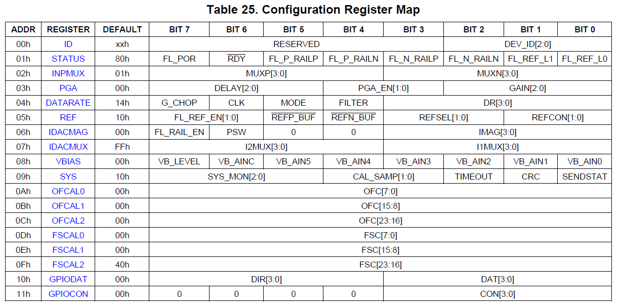
From the datasheet I understand DRDY must be low the moment RESET pin is help high along with START pin.

Here below my initialization code for ads124s08.

void ADS124s08_Initialize(void)
{
  uint8_t i, j, adcchannelnumber;
  /* clear buffers */
	for(j = eADC1; j < TotalNumberofADCs; j++)
	{
		for(i = 0; i < eTotalNumberOfRegADS124s08; i++)
		{
			ads124s08_register_data[j][i] = 0;
		}
	}
  
	for(i = 0; i < eTotalNumberOfRegADS124s08; i++)
	{
		ads124s08Registers[i] = 0;
	}

	for(i = 0; i < MAX_NO_OF_RTDs; i++)
	{
		ads124s08_raw_data[i] = 0;
		ads124s08_programmable_gain[i] = PGA_4;
		ads124s08_sample_rate[i] = DOR_400_0SPS;
	}

	for(channel = eADC1; channel < TotalNumberofADCs; channel ++)  // START pin held high
	{
		HAL_GPIO_WritePin(ADS_START[channel].port, ADS_START[channel].pin, GPIO_PIN_SET);
	}

	ADS124s08_DeselectAll(); // All chip select help high

	for(j = eADC1; j < TotalNumberofADCs; j++) //Given a RESET to all ads124s08
	{
		HAL_GPIO_WritePin(ADS_RESET[j].port, ADS_RESET[j].pin, GPIO_PIN_RESET);
		DelayMs(2);
		HAL_GPIO_WritePin(ADS_RESET[j].port, ADS_RESET[j].pin, GPIO_PIN_SET);
	}
		DelayMs(2);
	
	ADS124s08_reset_status_reg(); // Clear POR flag in status register

	__NOP();
	for (adcchannelnumber = eADC1; adcchannelnumber < TotalNumberofADCs; adcchannelnumber ++) //Set registers 
	{
		/* Set ADC for next MUX channel */
		ADS124s08_Sensor_Set(kADCMuxChannelTable[adcchannelnumber][0], DEFAULT_EXC);
		__NOP();
	}
	
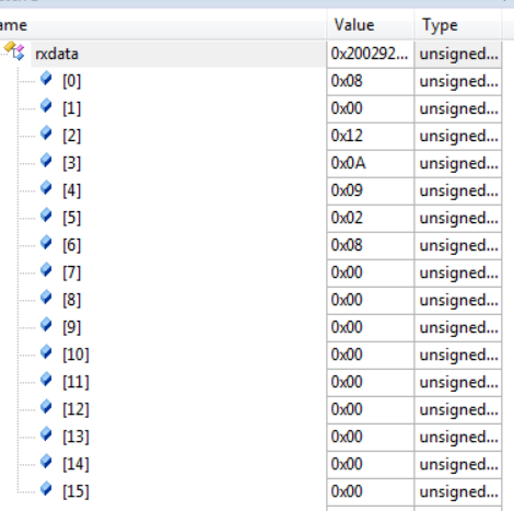
	ADS124s08_ReadRegisters(eADC1);
	ADS124s08_ReadRegisters(eADC2);
	ADS124s08_ReadRegisters(eADC3);
	ADS124s08_ReadRegisters(eADC4);
}

  • Hi Dhanaraj,

    Welcome to the forum!  How have you determined that the DRDY pin is not transitioning from high to low?  If the START pin is high, you should be able to put an oscilloscope probe on the DRDY pin and see it transition from high to low at the period of the selected data rate.

    You sent much of the setup code, but nothing regarding DRDY.  Are you polling DRDY or using an interrupt?  Have you verified that the GPIO is setup correctly?

    Best regards,

    Bob B

  • Hi Bob,

    Thanks for your response. I watch the DRDY pin through oscilloscope to see if there are any pulses. I have configured the DRDY pin as input.

    In my code I just poll the DRDY pin because I do not read the conversion data in the same ads124s08 sampling rate. This method was implemented by another engineer and I might want to ask, is there any difference in performance by setting high sampling rate(640sps) and read only few times(4 hz)?

    But my urgent issue is to bring up the board and ads124s08 is the only pending thing. Setting the register seems to be ok.

    
    	ads124s08Registers[ePGA] 	= (uint8_t)((ads124s08_programmable_gain[aSensor] << PGA_POS)|(PGA_EN << PGA_CTL_POS));
    	ads124s08Registers[eDATARATE]	= (uint8_t)(ads124s08_sample_rate[aSensor] << DOR_POS | (DOR_LOW_LATENCY_FILTER << DOR_FILTER_POS));
    	ads124s08Registers[eREF]	= (uint8_t)(( VREFCON_ON <<VREFCON_POS ));
    	ads124s08Registers[eIDACMAG] 	= (uint8_t)(IMAG_1500uA << IMAG_POS);
    	ads124s08Registers[eVBIAS] 	= (uint8_t)VBIAS_ZERO;
    	ads124s08Registers[eINPMUX] 	= (uint8_t)(( MUX_AIN1 <<MUX_SP_POS)|( MUX_AIN2 <<MUX_SN_POS));
    	if (ExcConfig == DEFAULT_EXC)
    	{
    	  ads124s08Registers[eIDACMUX]= (uint8_t)(( IDACMUX_AIN0<<I1MUX_POS)|( IDACMUX_DISCNT<<I2MUX_POS));
    	}
    	else
    	{
    	  ads124s08Registers[eIDACMUX]= (uint8_t)(( IDACMUX_DISCNT<<I1MUX_POS)|( IDACMUX_AIN0<<I2MUX_POS));
    	}
    
    static void ADS124x_SendREGs(uint8_t Select)
    {
    	if(Select < TotalNumberofADCs )
    	{
    		ADS124s08_SelectChip(Select);
    		ADS124x_BulkWrite((uint8_t)eINPMUX, NO_CONFIGURABLE_REG);
    		ADS124s08_DeselectChip(Select);
    	}
    }
    
    static void ADS124x_BulkWrite(uint8_t regAddr, uint8_t number)
    {
    	uint8_t bytestosend[eTotalNumberOfRegADS124s08],i;
    	uint8_t numbersofRegisters = number;
    	uint8_t regNo = regAddr;
    	i= 0;
    
    	if((number > 0) && (number + regAddr < eTotalNumberOfRegADS124s08))
    	{
    		bytestosend[i++] = cmdWREG|regAddr;
    		bytestosend[i++] = numbersofRegisters-1;
    
    		while(number > 0)	
    		{
    			number--;
    			bytestosend[i++] = ads124s08Registers[regNo++];
    		}
    
    		SPIx_Write(SPIdrv, bytestosend, i);
    	}
    }


  • Hi Dhanaraj,

    Unfortunately looking at your code for the register writes does not help me to determine much of anything.  It would be better to see scope or logic analyzer shots of the communication for verification.  This is the only truly reliable confirmation.

    If you are probing DRDY (as opposed to DOUT/DRDY), and START pin is high you should see DRDY toggle even at default register settings assuming that both AVDD-AVSS and DVDD are properly connected and powered. RESET must also be high.

    Best regards,

    Bob B