This thread has been locked.

If you have a related question, please click the "Ask a related question" button in the top right corner. The newly created question will be automatically linked to this question.

DAC8574: accuracy error

Part Number: DAC8574

Hello friends

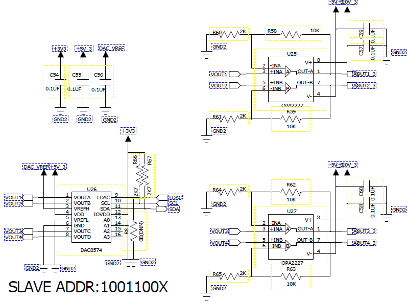
I am using dac8574 for my project and I have a controller tm4c123, the controller and dac have been interfaced using i2c vref of the dac is 5v and Vdd is also 5v and IO Vdd is 3.3 and I am not using LDAC

Vrefl is grounded and I am using 4 channels.

My problem is when I dont send anything on my I2c line then at the vout side of channel I am getting 0.0022v as an offset and when I send some voltage values on I2C line the output voltage is not much accurate then the input voltage which I am giving , it is lesser and error is arround 0.0018v and it increases as I increase the input voltage.

Is their any extra calculation should be done before sending that on my I2c

please reply

Regards

Harish

  • Hi Harish,

    What is the state of LDAC pin? Is it grounded? What command bytes are you sending to the DAC? Have you confirmed that the device is receiving the I2C frames correctly with an oscilloscope or logic analyzer?

    It may help to share your schematic as well.

    Thanks!
    Paul
  • Thank you for your reply Paul

    I have grounded the pin LDAC and I am using I2c as in burst mode in my controller. I have configured the slave address as 0x4c and since my sending my values to all the four channels the control bytes are configured as 0x10 ,0x12,0x14,0x16 for ch1 ,ch2 ,ch3 & ch4 respectively and the msb and lsb data values.

    Device is receiving the I2C frames correctly. The below is the dac part.

    Regards

    Harish

  • Hi Harish,

    I think I misunderstood your question originally.  I think you are getting nearly the correct value for the output range, but you are trying to understand the errors in output?

    When you power cycle the device the output should be at zero-code, which will have a Zero Code/Scale Error, which is generally different than the offset error as there is a 'headroom' limit on the output as the DAC is near the lowest potential supply (GND).  Once the output is away from the supply limit, the offset error comes a factor.  In addition, all DACs have a gain error, which will scale with the output value.  My colleague has a great video in the Precision DAC Learning Center describing the DAC errors you are seeing.  

    At about 2:30 in the video he describes the differences between FSE, OSE, and GE.  In addition, there is a section of the DAC8574 datasheet describing how to compensate for the output error called 'Digital Correction of DAC Errors'.  

    Please let me know if that answers your questions.

    Thanks!

    Paul

  • Thank you Paul that was really helpful and I didnt thought that their is so much of technicality behind this. I have seen your video which is really helpful, and I am try to adjust the dac error from that datasheet, Actually I am getting four different values with 0.02v difference rough in all the channels for example of I want 1 volt accross dac output then in channel 1 it is 1.012v and chnl2 it is 0.9978 in chnl 3 it is 1.0067 and in chnl 4 is 1.018v so I am getting confused that do i hv to adjust that dac error formula for all different chnl ?

    Regards
    Harish
  • Hi Harish,

    I'm glad the video helped! Each channel has it's own resistor ladder and buffer, so they will have independent gain and offset errors. It is possible that the GE will be similar for all channels as error in the shared reference voltage can look like a gain error in the output. You should implement a digital calibration for all channels individually. The Digital Correction of DAC Errors section of the device's datasheet should give you some insight in to this.

    Let me know if you have more questions about this.
    Paul