This thread has been locked.

If you have a related question, please click the "Ask a related question" button in the top right corner. The newly created question will be automatically linked to this question.

ADS1292: ECG Waveform not stable - Getting inverted QRS complex sometimes

Part Number: ADS1292

Hi all,

We are testing ECG using ADS1292 using ADS1292 breakout board.

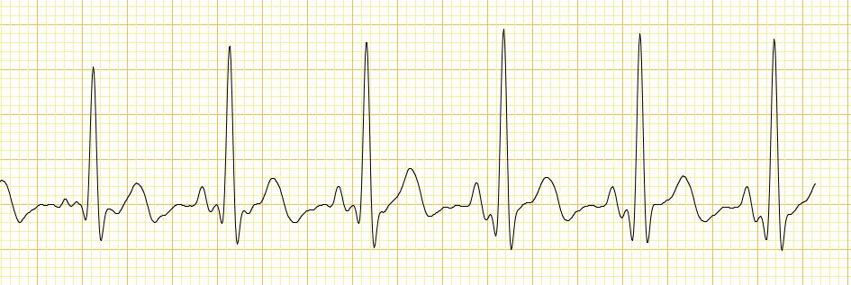
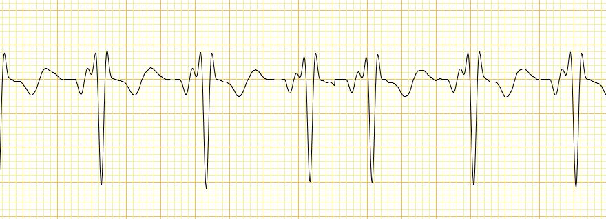
We are able to get the ECG waveforms correctly, but sometimes the QRS peak direction changes from positive to negative.
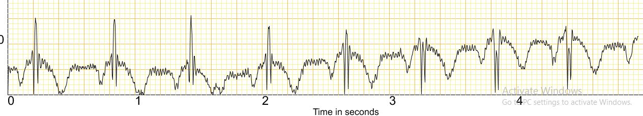
The shift from positive to negative peaks or vice versa happens gradually - i.e. The QRS peak reduces sample by sample before changing the peak direction completely.

Please find the attached waveforms for your reference.

Proper waveform - 

Waveform with negative peaks - 

Waveform during transition - 

Below are the register settings we are using :-

CONFIG1 - 0x00
CONFIG2 - 0xA0
LOFF - 0x10
CH1SET - 0x00
CH2SET - 0x00
RLDSENS - 0x2C
LOFFSENS - 0x00
RESP1 - 0x02
RESP2 - 0x03

We are reading ECG data from Channel 2 & are not using respiration currently. 
Also, we are observing the same behavior at different gains as well as sampling frequency.

What can be the reason for this issue ?
Since we are using off the shelf board, we think board design & layout can not be the cause for this. 
Are the register configuration correct ? 

Please advice. 
Looking forward to your valuable suggestions. 

Thanks,
Suresha

  • Hello Suresha,

    Thank you for your interest in our ADS1292!

    This is the first time that I've seen this breakout board. Do you have all three electrodes connected (i.e. RA, LA, and RLD)? I do not see any problems with your register settings. Are you sure that your code is converting the binary two's complement data correctly?

    I'm by no means a medical expert, but I do know that there are several factors which can affect the direction of the QRS complex. One such factor is the orientation of the heart's electrical axis. The orientation of the QRS complex will then depend on how the ECG leads are placed relative to that axis.

    To rule out any other causes first, I would connect a function generator to the LA and RA inputs on the breakout board. Be sure to share the ground connection with the breakout board ground.


    Best Regards,

  • Hi Ryan, 

    Thanks a lot for your response.

    We have connected all 3 electrodes i.e. RA , LA & RLD properly. In fact, we can see the effect of RLD on the ECG waveforms. The common mode noise reduces when we connect the RLD electrode. 
    Along with the ADS1292 breakout board, we also have a custom board. But the ECG waveform issue is present in both the boards. 
    Also, we are taking care of the two's complement data. But even when the QRS peak gets inverted, the raw data ADC is always positive (Between 0x000000 to 0x7FFFFF). 

    With respect to electrical axis, we consulted Echo technicians during testing.
    They looked at the position of the electrodes (On the Left & Right Arm) & confirmed that the QRS complex should always be positive. 
    Also, the QRS Complex goes negative randomly, without changing the position of the probes.

    We had implemented a ECG waveform simulator using a small micro-controller EVM.
    With this setup, we are observing proper positive QRS complex always without any issues.

    During further debugging today, we came across "Baseline wander" in ECG signals.
    To confirm that the issue is related to baseline wander, we implemented a 5Hz High Pass filter.
    With this filter, we neither see any variation in the ECG signal base level nor any negative QRS complex. 

    But this filter also removes P & T waves which is a concern. 
    Below is the snapshot of the waveform we are getting with 5Hz High Pass Filter.

    We are trying to fine tune the filter in with cutoff frequency in range of 0.5Hz to 1Hz.
    But this might have its own challenges, since cutoff frequency requirement may vary from patient to patient depending on the heart rate. 

    I have couple of questions with respect to this :- 

    1) Do you agree with our analysis regarding baseline wander ?
    2) Can you please suggest any alternate methods to remove the baseline wander ?

    Looking forward to your support.

    Thanks,
    Suresha 


  • Hello Suresha,

    Thanks for the detailed update.

    I do understand the impact of baseline wander ECG and, for that, a high-pass filter certainly makes sense. The cutoff frequency should be less than 1Hz. This requirement should not vary depending on the patient's heart rate. Although the heart rate is, say, 60bpm (i.e. one beat per second or 1Hz), the frequency content of the ECG waveform typically ranges from 0.05Hz to 150Hz. You could probably place the high-pass cutoff around 0.05Hz and better preserve the P and T waves while removing the baseline wandering.

    From a physiological standpoint, I do not understand how a change in the ECG baseline can cause the QRS complex to change direction. Perhaps that's something I need to learn more about myself.

    Best Regards,