This thread has been locked.

If you have a related question, please click the "Ask a related question" button in the top right corner. The newly created question will be automatically linked to this question.

ADS1299EEGFE-PDK: Bias Drive Circuit

Part Number: ADS1299EEGFE-PDK
Other Parts Discussed in Thread: ADS1299

Hi

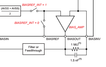
In datasheet bias drive feed back capacitor and resistor typical values are stated as 1,5nF nad 1MOhm. But they were picked as 392kOhm and 10nF in ADS1299EEGFE-PDK.

I calculated gain and cut-off frecuency for both.
For 1Mohm and 1,5nF: 106 Hz Fc and ~66 gain (at 50Hz)
For 392kOhm and 10nF: 40 Hz Fc and ~18 gain (at 50Hz)

Why 392kOhm and 10nF were used in ADS1299EEGFE-PDK ? Are 1Mohm and 1,5nF not better solution?

I measure very high interference at 50 Hz. (10mVpp). Are R and C values the source of the problem may be?

  • Hello Mustafa,

    Thank you for your interest in our ADS1299!

    You are correct that 1.5nF || 1M is a more appropriate solution. The goal should be to set the closed-loop bandwidth of the BIAS amplifier to be greater than 50 Hz / 60 Hz interference as well as at least the second harmonic. This way, the BIAS amplifier has a higher gain at those frequencies and provides a stronger common-mode cancellation signal to the body.

    The EVM was designed a few years ago, but if we ever update the hardware, we will be sure to include this change as well.

    Best Regards,