Other Parts Discussed in Thread: TMS320F28377S
Hi everyone
I'm use DAC8563, and i follow the data sheet to drive the DAC8563, but it cannot work and doesn't have any output signal
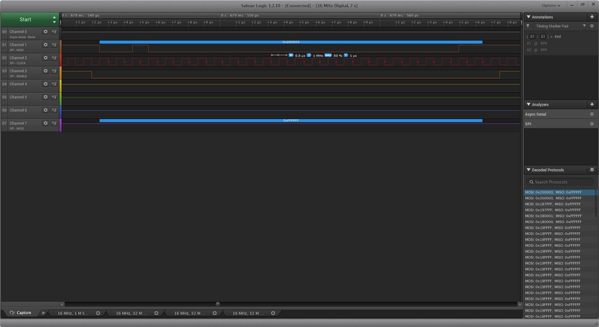
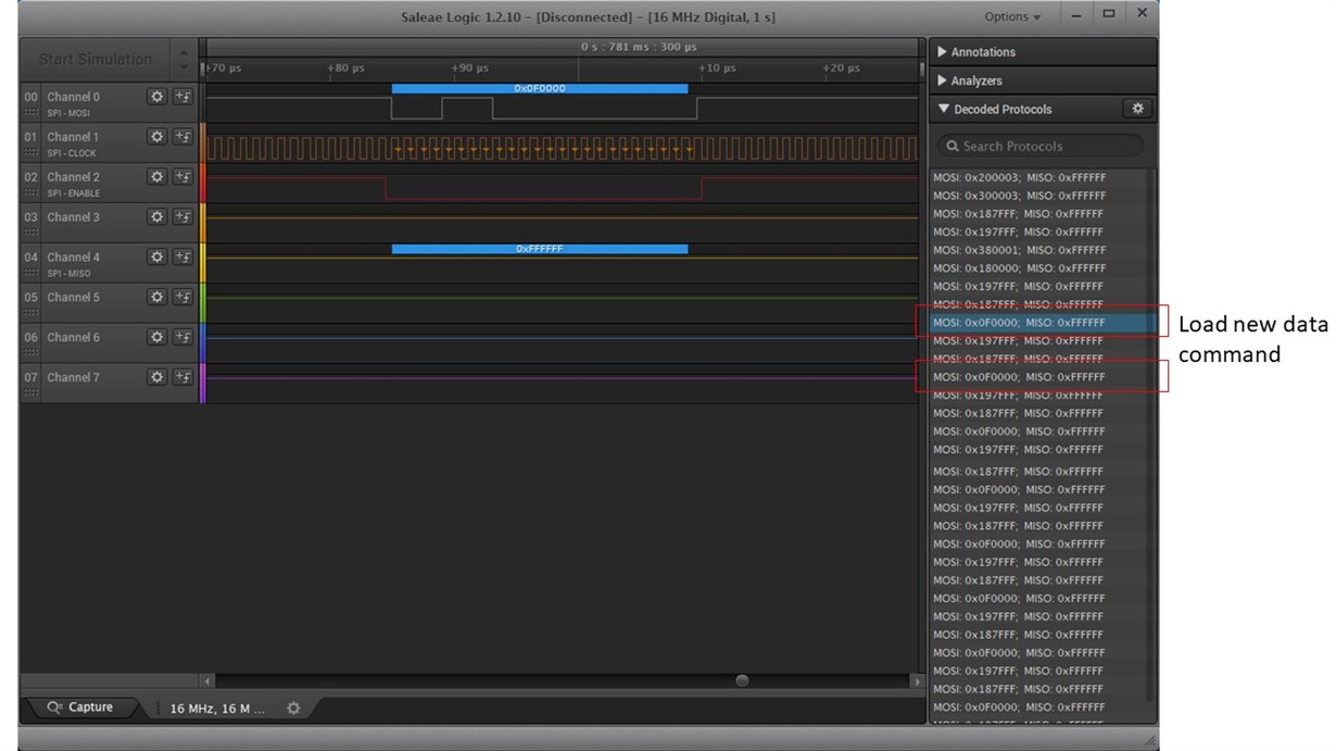
i'm coding the SPI progam in the LaunchPadXL TMS320F28377S below is the 2MHz SPI signal which is up date every 10ms of the SPI data (this prob data is form the micro controller reset)
the connection pin on the DAC8563 of the LDAC and CLR is to the ground
it's seems every thing is fine, but DAC8563 cannot work!! Please help me.
//###########################################################################
//
// FILE:   McBSP_SPI_DLB.c
//
// TITLE:  McBSP Loopback using SPI mode
//
//! \addtogroup cpu01_example_list
//! <h1>McBSP Loopback using SPI mode (mcbsp_spi_loopback)</h1>
//!
//!  This program will execute and transmit words until terminated by the user.
//!  SPI master mode transfer of 32-bit word size with digital loopback
//!  enabled.
//!
//!  \b McBSP \b Signals - \b SPI \b equivalent
//!  - MCLKX - SPICLK  (master)
//!  - MFSX  - SPISTE  (master)
//!  - MDX   - SPISIMO
//!  - MCLKR - SPICLK  (slave - not used for this example)
//!  - MFSR  - SPISTE  (slave - not used for this example)
//!  - MDR   - SPISOMI (not used for this example)
//!
//!  By default for the McBSP examples, the McBSP sample rate generator (SRG)
//!  input clock frequency is LSPCLK 80E6/4.
//!
//! \b Watch \b Variables: \n
//! - sdata1 - Sent data word(1)
//! - sdata2 - Sent data word(2)
//! - rdata1 - Received data word(1)
//! - rdata2 - Received data word(2)
//!
//
//###########################################################################
// $TI Release: F2837xS Support Library v210 $
// $Release Date: Tue Nov  1 15:35:23 CDT 2016 $
// $Copyright: Copyright (C) 2014-2016 Texas Instruments Incorporated -
//             http://www.ti.com/ ALL RIGHTS RESERVED $
//###########################################################################

//
// Included Files
//
#include "F28x_Project.h"
#include "main.h"

//
// Globals
//
Uint16 sdata1 = 0x000;    // Sent Data
Uint16 rdata1 = 0x000;    // Received Data
Uint16 sdata2 = 0x000;    // Sent Data
Uint16 rdata2 = 0x000;    // Received Data
Uint16 usDacValue = 0x000;
char cmd_state = 0x00;

//
// Function Prototypes
//
__interrupt void cpu_timer0_isr(void);
__interrupt void Mcbsp_TxINTA_ISR(void);
//__interrupt void Mcbsp_RxINTA_ISR(void);

void init_mcbsp_spi(void);
void mcbsp_xmit(int a, int b);
void DAC8562_SetData(char _ch, Uint16 _dac);
void bsp_InitDAC8562(void);
void PinOutInit(void);
void error(void);

//
// Main
//
void main(void)
{
//
// Step 1. Initialize System Control:
// PLL, WatchDog, enable Peripheral Clocks
// This example function is found in the F2837xS_SysCtrl.c file.
//
   InitSysCtrl();

//
// Step 2. Initialize GPIO:
// This example function is found in the F2837xS_Gpio.c file and
// illustrates how to set the GPIO to it's default state.
// For this example, only enable the GPIO for McBSP-A
//
   InitMcbspaGpio();
   PinOutInit();

//
// Step 3. Clear all interrupts and initialize PIE vector table:
// Disable CPU interrupts
//
   DINT;

//
// Initialize PIE control registers to their default state.
// The default state is all PIE interrupts disabled and flags
// are cleared.
// This function is found in the F2837xS_PieCtrl.c file.
//
   InitPieCtrl();

//
// Disable CPU interrupts and clear all CPU interrupt flags:
//
   IER = 0x0000;
   IFR = 0x0000;

//
// Initialize the PIE vector table with pointers to the shell Interrupt
// Service Routines (ISR).
// This will populate the entire table, even if the interrupt
// is not used in this example.  This is useful for debug purposes.
// The shell ISR routines are found in F2837xS_DefaultIsr.c.
// This function is found in F2837xS_PieVect.c.
//
   InitPieVectTable();


//
// Interrupts that are used in this example are re-mapped to
// ISR functions found within this file.
//
   EALLOW;    // Allow access to EALLOW protected registers
   PieVectTable.TIMER0_INT = &cpu_timer0_isr;
   //PieVectTable.MCBSPA_RX_INT = &Mcbsp_RxINTA_ISR;
   PieVectTable.MCBSPA_TX_INT = &Mcbsp_TxINTA_ISR;
   EDIS;      // Disable access to EALLOW protected registers

//
// Step 4. User specific code
//
   init_mcbsp_spi();
   InitCpuTimers();

//
// Configure CPU-Timer 0, 1, and 2 to interrupt every second:
// 200MHz CPU Freq, 1 second Period (in uSeconds)
//
   ConfigCpuTimer(&CpuTimer0, 200, 10000);

//
// To ensure precise timing, use write-only instructions to write to the
// entire register. Therefore, if any of the configuration bits are changed in
// ConfigCpuTimer and InitCpuTimers (in F2837xS_cputimervars.h), the below
// settings must also be updated.
//
   CpuTimer0Regs.TCR.all = 0x4000;
//   CpuTimer1Regs.TCR.all = 0x4000;
//   CpuTimer2Regs.TCR.all = 0x4000;


//
// Enable interrupts required for this example
//
   PieCtrlRegs.PIECTRL.bit.ENPIE = 1;   // Enable the PIE block
   PieCtrlRegs.PIEIER6.bit.INTx5 = 1;   // Enable PIE Group 6, INT 5
   PieCtrlRegs.PIEIER6.bit.INTx6 = 1;   // Enable PIE Group 6, INT 6

//
// Enable TINT0 in the PIE: Group 1 interrupt 7
//
   PieCtrlRegs.PIEIER1.bit.INTx7 = 1;

//   IER = 0x20;                          // Enable CPU INT6
   IER |= M_INT6;
//
// Enable CPU int1 which is connected to CPU-Timer 0, CPU int13
// which is connected to CPU-Timer 1, and CPU int 14, which is connected
// to CPU-Timer 2:
//
   IER |= M_INT1;
//   IER |= M_INT13;
//   IER |= M_INT14;
   EINT;                                // Enable Global Interrupts


   sdata1 = 0xAAAA;
   sdata2 = 0xAA;

   usDacValue = 32768;
   //bsp_InitDAC8562();
//
// Main loop to transfer 32-bit words through MCBSP in SPI mode periodically
//
   for(;;)
   {
	   //mcbsp_xmit(sdata1,sdata2);
	   //DAC8562_SetData(0, usDacValue);

        //
        // Master waits until RX data is ready
        //
        //while( McbspaRegs.SPCR1.bit.RRDY == 0 ) {}
        rdata2 = McbspaRegs.DRR2.all;   // Read DRR2 first.
        rdata1 = McbspaRegs.DRR1.all;   // Then read DRR1 to complete
                                        // receiving of data.

        //
        // Check that correct data is received.
        //
        if((rdata2 != sdata2)&&(rdata1 != sdata1))
        {
            //error( );
        }

        delay_loop();

        //sdata1^=0xFFFF;
        //sdata2^=0xFF;

       __asm("    nop");                // Good place for a breakpoint
   }
}


//
// error - Error function to halt debugger
//
void error(void)
{
   __asm("     ESTOP0");  // test failed!! Stop!
    for (;;);
}

//
// init_mcbsp_spi - Configure McBSP settings
//
void init_mcbsp_spi()
{
    //
    // McBSP-A register settings
    //
    McbspaRegs.SPCR2.all = 0x0000;       // Reset FS generator, sample rate
                                         // generator & transmitter
    McbspaRegs.SPCR1.all = 0x0000;       // Reset Receiver, Right justify word,
                                         // Digital loopback dis.
    McbspaRegs.PCR.all = 0x0F08;         //(CLKXM=CLKRM=FSXM=FSRM= 1, FSXP = 1)
    McbspaRegs.SPCR1.bit.DLB = 1;
    McbspaRegs.SPCR1.bit.CLKSTP = 0x02;     // Together with CLKXP/CLKRP
                                         // determines clocking scheme
    McbspaRegs.PCR.bit.CLKXP = 0;        // CPOL = 0, CPHA = 0 rising edge
                                         // no delay
    McbspaRegs.PCR.bit.CLKRP = 0;
    McbspaRegs.RCR2.bit.RDATDLY = 01;    // FSX setup time 1 in master mode.
                                         // 0 for slave mode (Receive)
    McbspaRegs.XCR2.bit.XDATDLY = 01;    // FSX setup time 1 in master mode.
                                         // 0 for slave mode (Transmit)

    //McbspaRegs.RCR1.bit.RWDLEN1 = 4;     // 32-bit word
    //McbspaRegs.XCR1.bit.XWDLEN1 = 4;     // 32-bit word
    InitMcbspa24bit();

    McbspaRegs.SRGR2.all = 0x2000;       // CLKSM=1, FPER = 1 CLKG periods
    //McbspaRegs.SRGR1.all = 0x000F;       // Frame Width = 1 CLKG period,
                                         // CLKGDV=16
    McbspaRegs.SRGR1.all = 0x0032;			//SPI in 1Mhz for test
    //McbspaRegs.SRGR1.all = 0x0000;		//SPI in 50Mhz

    McbspaRegs.MFFINT.bit.XINT = 1; // Enable Transmit Interrupts

    McbspaRegs.SPCR2.bit.GRST = 1;       // Enable the sample rate generator
    delay_loop();                        // Wait at least 2 SRG clock cycles
    McbspaRegs.SPCR2.bit.XRST = 1;       // Release TX from Reset
    McbspaRegs.SPCR1.bit.RRST = 1;       // Release RX from Reset
    McbspaRegs.SPCR2.bit.FRST = 1;       // Frame Sync Generator reset
}

//
// mcbsp_xmit - Transmit MCBSP data
//
void mcbsp_xmit(int a, int b)
{
    McbspaRegs.DXR2.all = b;
    McbspaRegs.DXR1.all = a;
}


void DAC8562_SetData(char _ch, Uint16 _dac)
{
	if (_ch == 0)
	{
		/* Write to DAC-A input register and update DAC-A; */
		McbspaRegs.DXR2.all = (3 << 3);
		McbspaRegs.DXR1.all = (_dac << 0);
	}
	else if (_ch == 1)
	{
		/* Write to DAC-B input register and update DAC-A; */
		McbspaRegs.DXR2.all = (3 << 3)|(1 << 0);
		McbspaRegs.DXR1.all = (_dac << 0);
	}
}

void bsp_InitDAC8562_PwrUP(void)
{
	if(ENUM_DACINIT == cmd_state)
	{
		cmd_state = ENUM_DACPWRUP;
	}

	else if(ENUM_DACPWRUP == cmd_state)
	{
		/*Power up DAC-A and DAC-B */
		/* DAC8562_WriteCmd((4 << 19) | (0 << 16) | (3 << 0)); */
		McbspaRegs.DXR2.all = (4 << 3);
		McbspaRegs.DXR1.all = (3 << 0);

		cmd_state = ENUM_DACSETUP_LOAD;
	}

	else if(ENUM_DACSETUP_LOAD == cmd_state)
	{
		/* LDAC pin inactive for DAC-A and DAC-B */
		/* DAC8562_WriteCmd((6 << 19) | (0 << 16) | (3 << 0)); */
		McbspaRegs.DXR2.all = (6 << 3);
		McbspaRegs.DXR1.all = (3 << 0);

		cmd_state = ENUM_DACSETCHA;
	}

	else if(ENUM_DACSETCHA == cmd_state)
	{
		DAC8562_SetData(0, 32767);

		cmd_state = ENUM_DACSETCHB;
	}

	else if(ENUM_DACSETCHB == cmd_state)
	{
		DAC8562_SetData(1, 32767);

		cmd_state = ENUM_DACSETUP_GAIN;
	}

	else if(ENUM_DACSETUP_GAIN == cmd_state)
	{
		/* Select GAIN = 2 */
		/*DAC8562_WriteCmd((7 << 19) | (0 << 16) | (1 << 0)); */
		McbspaRegs.DXR2.all = (7 << 3);
		McbspaRegs.DXR1.all = (1 << 0);

		cmd_state = ENUM_PWRCOMPLETE;
	}

	else if(ENUM_PWRCOMPLETE == cmd_state)
	{
		DAC8562_SetData(0, 0);

		cmd_state = ENUM_DACRUN_CHA;
	}

	else if(ENUM_DACRUN_CHA == cmd_state)
	{
		DAC8562_SetData(1, 0xFFFF);

		cmd_state = ENUM_DACRUN_CHB;
	}

	else if(ENUM_DACRUN_CHB == cmd_state)
	{
		DAC8562_SetData(0, 0xFFFF);

		cmd_state = ENUM_DACRUN_CHA;
	}
}


//
// Mcbsp_TxINTA_ISR - Mcbsp Transmit ISR
//
__interrupt void Mcbsp_TxINTA_ISR(void)
{
    //
    // To receive more interrupts from this PIE group, acknowledge
    // this interrupt
    //
    PieCtrlRegs.PIEACK.all = PIEACK_GROUP6;
}


//
// cpu_timer0_isr - CPU Timer0 ISR with interrupt counterxx
//
__interrupt void cpu_timer0_isr(void)
{
   CpuTimer0.InterruptCount++;
   GpioDataRegs.GPATOGGLE.bit.GPIO12 = 1;
   GpioDataRegs.GPATOGGLE.bit.GPIO13 = 1;

   bsp_InitDAC8562_PwrUP();

   PieCtrlRegs.PIEACK.all = PIEACK_GROUP1;
}

void PinOutInit(void)
{
	GPIO_SetupPinMux(12, GPIO_MUX_CPU1, 0);
	GPIO_SetupPinOptions(12, GPIO_OUTPUT, GPIO_PUSHPULL);

	GPIO_SetupPinMux(13, GPIO_MUX_CPU1, 0);
	GPIO_SetupPinOptions(13, GPIO_OUTPUT, GPIO_PUSHPULL);

}


