This thread has been locked.

If you have a related question, please click the "Ask a related question" button in the top right corner. The newly created question will be automatically linked to this question.

PGA970: PGA970 4-wire connection question

Part Number: PGA970
Other Parts Discussed in Thread: USB2ANY

Hi team,

The customer would like to use PGA970.

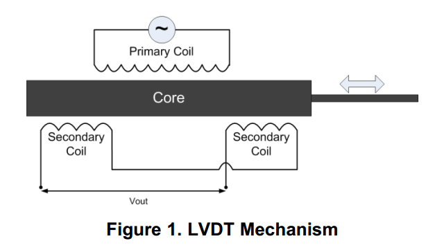
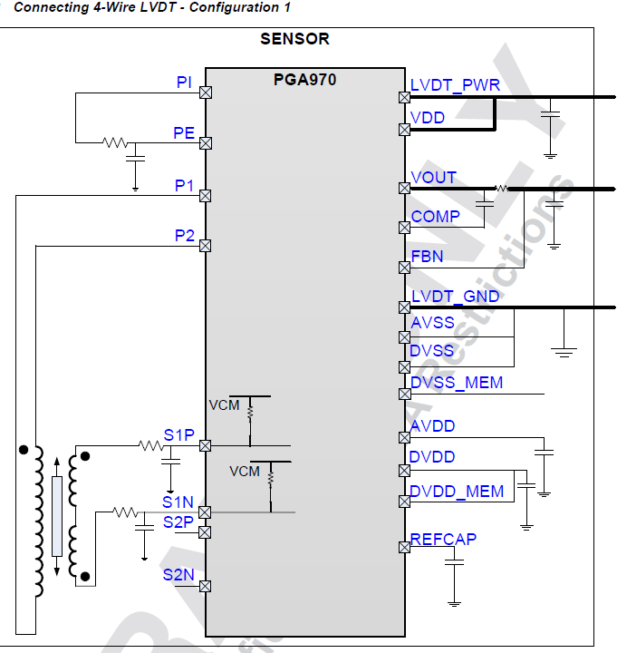
Q1: There are 4 wires for the LVDT sensor. Would you explain how to connect the 4 wires LVDT sensor for PGA970?

Like the attach connection?

Q2: The customer would like to only use SPI to program, not use the internal ARM-Cortex M0. Is this achieved?

Q3: The customer has a PGA970EVM board. But the USB2ANY is burned when he tests the EVM. So he uses STM32 to connect

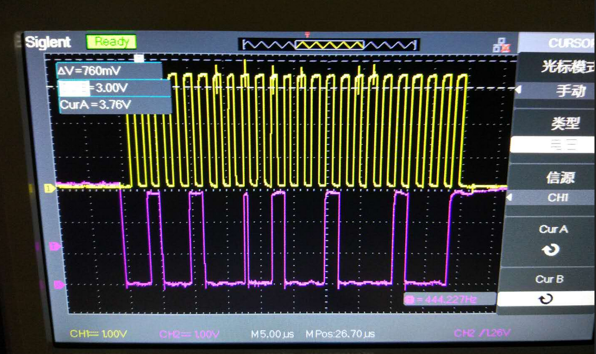
PGA970EVM. He tests the SCK pin waveform and the MISO pin waveform through the oscilloscope. 

Please check the attach. The yellow waveform is the  SCK pin waveform. The purple waveform is the MISO pin waveform.

The SCK pin waveform is fine. And the CS and MOSI waveforms are also fine. But it looks bad for the MISO pin waveform.

The customer would like to verify if his operation of SPI exists the error or maybe the MISO pin is burned when he tests the EVM.

Best Wishes,
Mickey Zhang
Asia Customer Support Center
Texas Instruments

  • Hi Mickey,

    1. Yes, the recommended connection for a 4-wire sensor is as shown from the applications section of the datasheet.

    2. If the microcontroller is in reset, then all registers are available for read and write through SPI. However, if the microcontroller is running, the only way to access any registers is through the COMBUF which will need to work with the firmware programmed into the M0 microcontroller. If the customer would just like to read the ADC values from the registers, the microcontroller can remain in reset permanently.

    3. In this case it seems like the MISO pin may have been damaged in the event that broke the USB2ANY.

    Regards,
  • Hi Scott,

    Thanks for your help.

    For the 4-wire LVDT sensor connection, my attach is the 3 wire connection. The customer said his LVDT sensor is 4 wire, like the

    below attach. So, for the 4 wire LVDT sensor connection, how to connect it with PGA970? Would you verify it again?

    Which part of the datasheet is shown the 4-wire LVDT sensor connection?

  • Hi Mickey,

    Sorry about that. I had mistaken the diagram for a different one. The 4-wire sensor diagram is not shown in the production datasheet. I will post a diagram for you, but in the meantime, the two primary connections will hook up to pins P1 and P2, and the two secondary connections will hook up to pins S1P and S2P. The secondary connections are made similar to the 3 wire example above, while the primary is connected differently since it has 2 pins in the 4 wire sensor.


    Regards,

  • Hi Scott,

    OK. Thanks for your help. Would you send me the diagram for the 4-wire LVDT sensor connection?
  • Hi Mickey,

    There are actually two different configurations possible. One is the way that I described above with an additional short between the primary P2 and between the secondaries, and the other uses S1P and S1N for the secondary connections. See below: