


Other Parts Discussed in Thread: ADS1220,
Hello Support Team,
Well, I've been struggling for a while about this problem, and I'm now in a dead end : I can't manage reading back the configuration registers during the init of the component.
Of course the same problem arises during the data read sequence of the Pt100 temperature sensor (problem not exposed in this post but certainely closely related to).
The MOSI signal stays stuck at 0xFF whatever the content of the configuration regs.
To try to fix the problem, the DOUT/nDRDY signal has been isolated from the SPI bus and tied to a pull down resistor (10k). I'm using the bus decode option of the scope to monitor the results.
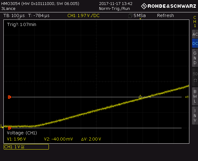
I've followed all the relevant posts related to ADS1120/ADS1220 so checked 1st the Power On ramp close to the VDD pin. The ramp is by far slower than 1V/50µs so POR doesn't seem to be the concern.

After POR, the firmware sends the init routine to the ADS1120 which acts as a loop (for debug purpose) in such this way :
A - wait 52ms
B - send a 0x06 Reset command
C - poll the DRDY signal and wait until it goes low
D - send a 5 byte configuration sequence : 0x43 Write command + 0x0A Conf Reg 0 + 0x00 Conf Reg 1 + 0x54 Conf Reg 2 + 0x70 Conf Reg 3
E - send a configuration readback sequence : 0x23 Read command followed by 5 0x00 Nop opcodes => the 5 read bytes should reflect the content of the previous written ones, but instead are all 0xFF
F - send a 0x08 Start command
G - poll the DRDY signal and waits until it goes low and loop back to A
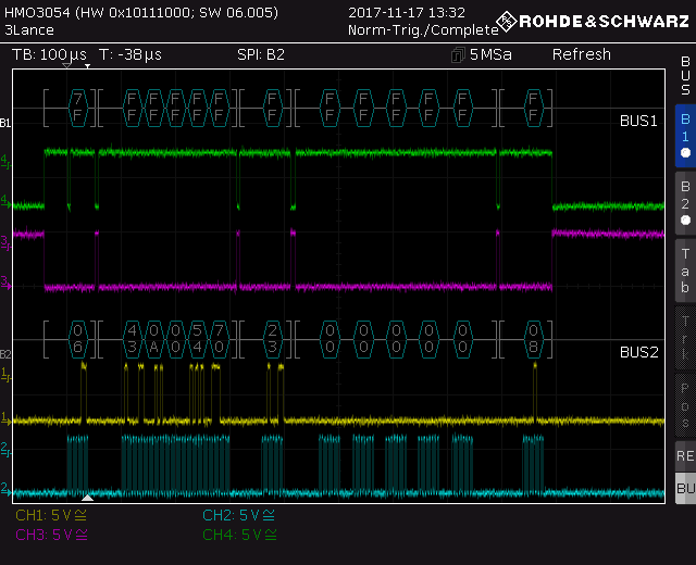
1st screenshot :
Blue : SPI clock
Yellow : SPI MOSI (DIN)
Magenta : nCS
Green : MISO (DOUT/nDRDY)
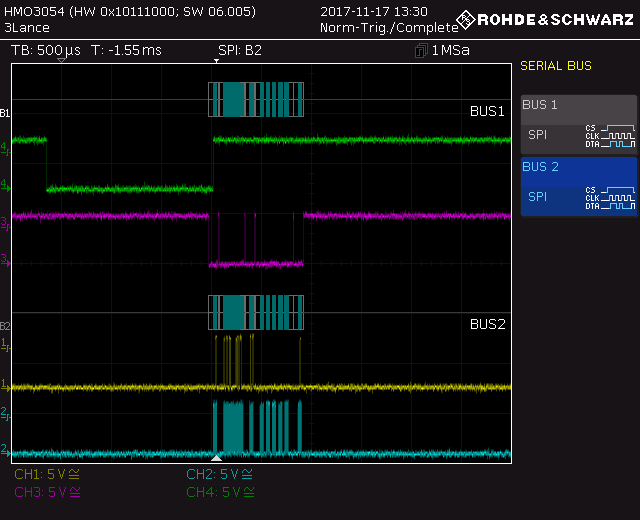
2nd screenshot :
Blue : SPI clock
Yellow : SPI MOSI (DIN)
Magenta : nCS
Green : DRDY
I have already replaced the ADS1120, same problem.
SPI MOSI, SPI CLOCK and SPI MISO are working well with the other components (3 * 4-20mA controller and 1 digital potentiometer) tied on the SPI bus. This is not a board issue.
The ADS1120 seems to be alive (DRDY signal is shifting each time a Reset or Start has been completed), however the DOUT/nDRDY is stuck.
Any idea ?
Regards,
Michel

