This thread has been locked.

If you have a related question, please click the "Ask a related question" button in the top right corner. The newly created question will be automatically linked to this question.

PGA Gain

Other Parts Discussed in Thread: ADS1299, ADS1299EEGFE-PDK

Hello everyone,

In ads1299 tha PGA is given as 1, 2, 4, 6,8,12,24....what's hapening when the following gains are selected??As am new to this area am struggling a lot with this PGA setting...I need to know whats happening behind this when the gain values are selected...As eeg signals requires thousands of gain and here the gain is given as 24 i am confused about the working....will anyone plz explain this in detail...thanks in advance

  • Hi LF!

    Welcome to our e2e forum! The easiest way to get started is to use the 'Search through...questions and answers' box at the top of the page. A simple search for 'EEG' will provide a number of options for you to get started using some previous posts in our forum. One such post is here:

    e2e.ti.com/.../222197

    For detail about the gain settings of the ADS1299 and how that relates to the analog input voltage and the reference, you can begin with section 9.3.1.2 in the ADS1299 datasheet (page 22).
  • Hello sir
    Thank you for your valuable replies... Actually am trying to acquire emg signal using ads1299 eeg-fe kit...initially i have to check the kit with a sine wave given as external input using function generator...how i have to check with??
  • Hi LF,

    Please review sections 4.6.1 and 4.6.2 of the ADS1299EEGFE-PDK Users Guide (www.ti.com/.../slau443b.pdf). Those section step you through the process of applying a sine wave to the inputs of the ADS1299.
  • Sir
    Thank you...am having a doubt about PGA gain...if am giving 10micro volt as input and selecting gain of 24 what will be the output voltage... Whether it's 24times the input voltage, means 240 microvolt
  • Hi LF,

    Yes, that is correct. Because of the low noise floor in the ADS1299 though, the PGA gain settings are often high enough to get adequate resolution from intracranial and scalp based electrodes. If higher gain is required, you can certainly use an amplifier stage ahead of the ADS1299 to boost the signal before digitizing it.
  • Thank you sir...in the  above discussion for checking with external sine wave u ask me to refer section 4.6.1 and 4.6.2...Initially i have to check with single ended input..for this am selecting only one channel...i.e channel 1...if i use function generator(FG) to give external input shall i connect the positive side of FG to pin 36 and negative side to pin 34 of J6 and set SRB1 register close??...is this enough or i have to do more settings??

  • Hi LF,

    Please refer to the schematic on page 51 of the users guide.  There are a series of shunt jumpers installed on J6 which feed into the AINxN and AINxP pins of the ADS1299.  Remove the shunts which correspond to the AINxP signals, which would be the one across pins 7-8, 11-12, etc down through pins 35-36.  Put shunt jumpers across pins 1-2 and 5-6 on JP-25.  From there, your signal generator reference (GND) can be connected to TP12.  The signal generator output can be applied to J6 pins 8, 12, 16 etc through pin 36. 

  • Thank you sir..what is the input amplitude range of ads1299 EEG-FE kit??

  • Sir i have tried with some input...i have set Vpp as 1V and frequency as 80.7 Hz using CRO and function generator...the settings in ADS1299 EEG-FE kit are as follows

    1. use single ended input

    2.  remove jumpers from 32-36 of J6 and connect the positive of function generator to pin 36 of J6 and ground to pin 34 of J6.

    3.  Set SRB1 bit closed

    4.  Set PGA gain to 1

    5. Checked with sine wave as input

    But i didnt get sine wave as expected...i have got some other waveform...plz explain what is wrong with me..either the settings or connections??let me post the image below...

  • Hi LF!

    The analog input range to the ADS1299EEGFE-PDK is the same as the actual device itself, which is +/-Vref/gain. I'll try to get a setup in our lab running with a similar input as you described above just to verify various jumper and register settings noted in the Users Guide. Give me a day or two and we'll do what we can to resolve this as soon as possible.
  • Thank you sir...am waiting for ur reply

  • Hi LF,

    I was setting up the EVM with Tom, We did not experience any distortion or abnormalities in the FFT. Two things we did to get a clean signal was provide an offset of 2.5V to the sine wave, that way the signal is not close to the lower -VREF. Also, the sampling rate was set to 250SPS in your setup. This is very close the Nyquist Sampling:

    1/80.7 = 0.0124 * 2 = 0.02478

    Changing the sample rate to 1000SPS will give you a better sampled signal.
  • Thank you sir..if u don't mind can u plz upload the image of ur output

  • Thank you sir..will try and come with my results tomorrow

  • Hi LF,

    Here are the screenshots of my signal. I took both 250SPS and 1000SPS so you can see the difference

    Sine, 80.7 Hz, Offset 1.125 V, Amplitude 1 Vrms

    250SPS

    1000SPS


  • Sir I have 2 doubts

    1)First one is u have given some calculation... It is known that fs>=2*f...in my signal f=80.7Hz.

    In ur calculation u calculated time from frequency f and my doubt is for what purpose u multiply the time by 2?

    2)Second doubt is how to set offset voltage?

    Plz help me to understand these concepts sir

  • Hi LF,
    To clarify about the sampling rate, 250 SPS is not Nquist of 80.7 Hz, but it's such a slow data rate that you can easily see that it is aliasing the signal. As you increase the SPS to 1000, 2000, etc the signal will be look better.

    As for the offset, i did not mention that i was performing the measurement with uni-polar (0 - 5 V). when this is done, and SRB1 is closed it bias the negative supply to 2.5 V. This makes sure that you are at the center of Vref and you won't be clipping the positive or negative supply. As a result, i applied a 2.5 V offset to my sine wave, so the differential between positive and negative supply is the sine wave exclusively. On my signal generator the signal was not 50 Ohm terminated so I had to half the desired voltage I needed. but if your signal gen is properly terminated you can use 2.5 V.

    Hope this clarifies.
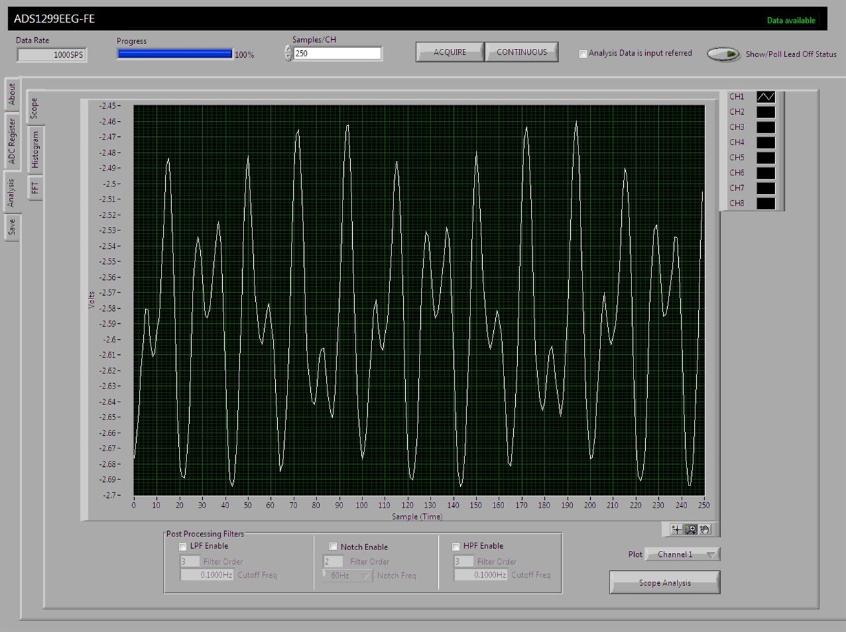
  • Thank you sir for ur valuable replies....today i tried with 1000SPS, Vpp-1, gain-1 and f=89.7 Hz ...but am not sure about 50 ohm terminator ...how i have to check whether the function generator has 50 ohm terminator...and the important thing is suppose the function gen has no 50 ohm terminator how i have to reduce the offset voltage from 2.5v to 1.125v...I have uploaded the output what i got today with the above mentioned values...what is  mistake with this output sir?


  • LF,

    Are you using unipolar or bipolar power supply? Your graph results are very bizarre because your median voltage over where the signal is oscillating is at -2.5 V. Whereas the part's spec that -2.5 V is the negative supply cuttoff. Do you have another signal generator you can try? Because it looks like there are several sine waves being sent, it does not look like harmonics from your graph. Thankfully, the 1k SPS is providing a clean reading. the first thing I would do is try and get the sine wave to 0 V.
  • Sir am using unipolar supply.. And the input I used is single ended...I gave the positive terminal of function generator to pin 36 of J6 and ground terminal to 34 of J6 and make SRB1 closed...the gain I used is 1...what can I do for reducing the offset voltage from 2.5v to 1.125v??

  • In your signal generator set the offset voltage to 1.25 V. (2.5 V / 2)