I am using Arduino UNO and its library for ads1299. My issue is I am getting dynamic ID. Following is my screenshot of output.
This thread has been locked.
If you have a related question, please click the "Ask a related question" button in the top right corner. The newly created question will be automatically linked to this question.
I am using Arduino UNO and its library for ads1299. My issue is I am getting dynamic ID. Following is my screenshot of output.
Thank you so much for replying. Really appreciate that.
My power was not enough so I connected extra battery with the ads1299 and got this output. I have connected the RESET pin to 3.3 Volts and using RESET Command for the reseting the ADS1299.
Now the problem is that I am not getting 1.1 Volts at VCAP1. Is it normal to get default values of registers without getting the 1.1 Volts at VCAP1?
Thank You once again waiting for your reply sir.
Thank so much sir for your response.
My analog power supply voltages are 5 V vdd and ground vss. I am using single supply. While my digital power is 3.3 volts and ground.
I am sending the RESET command through arduino and getting above register values. My ID is 0x20. Is it normal???
Plus my voltage at VCAP1 is 0.1 to 0.25 volts.
Regards
Mubeen
I have plotted my output signal its is just a noise nothing else . I have applied 100 hz 1 volt signal and its giving random values.
Moreover, my ads1299 sampling rate is not 16K sps as set in config2 register. I am taking output at DRDY pin and its giving 55Khz pulse.
My vcap1 voltage is never 1.1 volts.
I just have no idea what is going really need your help sir.
Regards Mubeen.
Hey Tom Thank You so much for your patience.
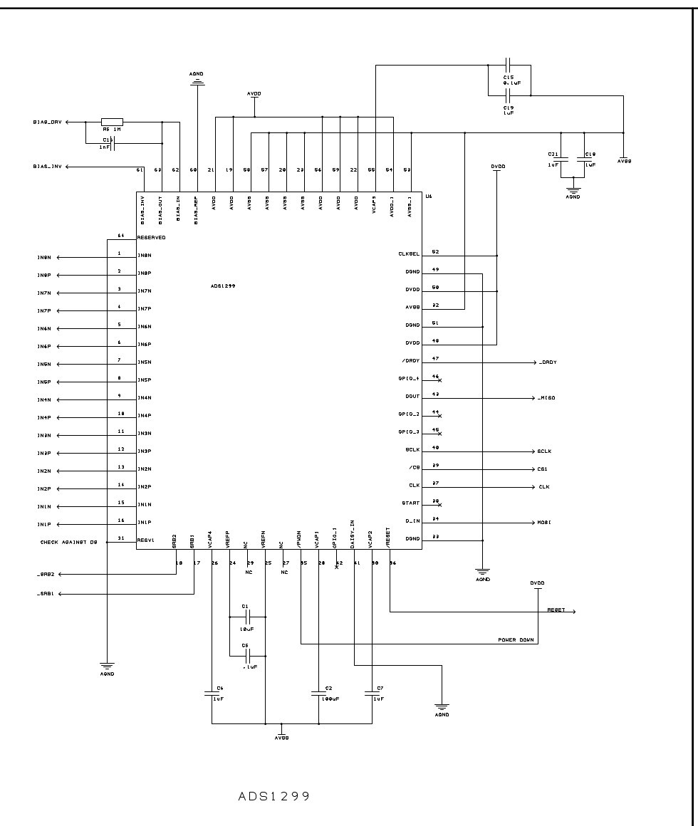
I made all circuit on New Vero board and connected constant voltage sources of 5Volt and 3.3Volts. But the problem is same I am getting 0x20 ID. When I connect my ground to the micro controller ground directly, all register values become 0x00. While if i connect a 10k resistor in series it start showing reset values and ID remains 0x20. I can write all registers except the last 4 channels. Here is the schematic I followed.
Hi again!
So...where does AVSS, AVDD and DVDD go relative to AGND, the 5 and 3.3V power and the signals to your micro? Can you draw them in here as well for a more complete schematic?
Hi tom,
My AVDD , AVSS, AVSS1 are from a 5V buck while all the digital part is from 3.3 Volt buck. While signals are going to the Microcntroller Arduino and I am using ADS1299 Arduino library for operting it. I am using a unipolar supply so shorted AVSS with AGND.