Because of the Thanksgiving holiday in the U.S., TI E2E™ design support forum responses may be delayed from November 25 through December 2. Thank you for your patience.

This thread has been locked.

If you have a related question, please click the "Ask a related question" button in the top right corner. The newly created question will be automatically linked to this question.

ADC12D500RF: ADC12D500RF temperature sensor diode don't work

Part Number: ADC12D500RF
Other Parts Discussed in Thread: LM95214, LM95233

I have two ADC ADC12D500RF, FPGA Kintex and temperature monitor LM95214 on board. LM95214 correct measure temperature FPGA and LM95214 internal/local temperature, but ADC12D500RF sensors return code 0x7F (MSB) or 127 °C (0x7FF with MSB and LSB). But real ADC package temperature 31 °C. Data Sheet on ADC12D500RF not contain characteristics for die diode sensor. How decode LM95214 temperature information from ADC ADC12D500RF diode sensor?

Thank you for support!

Alexander

  º

  • Hi Alexander
    Can you share a schematic showing connections between the LM95214 and external diodes (FPGA and ADC), including any capacitors, etc?
    The ADC12D500RF thermal diode has been validated using the LM95233 remote diode temperature sensor so I would expect the LM95214 results would be similar.
    Best regards,
    Jim B
  • Hi Jim!

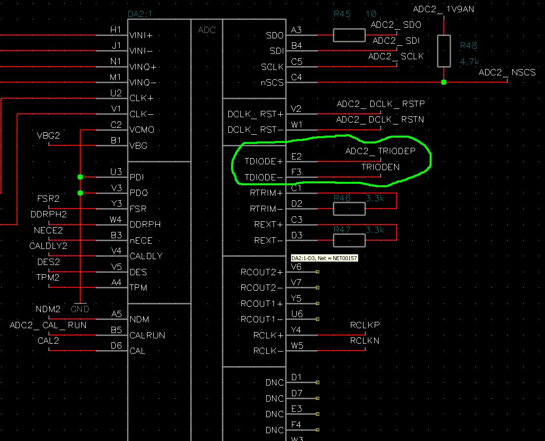
    Show my schematic connection between ADC12D500RF and LM95214:

    ADC Page

    LM95214 Page

    Thank you for support!

    Alexander

  • Hi Jim!
    If ADC not powered then take place temperature +127 °C (as described above). After power on ADC, temperature show nearly +100 °C without cooling and +90 °C with cooling. This temperature is normal for ADC ADC12D500RF (ADC powered, but not start)?

    Best regards,
    Alexander
  • Hi Alexander
    If the ADC is powered then the temperature can rise significantly depending on how well heat is coupled from the device to the circuit board ground planes and to ambient air. There must be good coupling from the center GND balls to the board ground planes to help facilitate coupling. See datasheet Section 6.4.5.5 Thermal Management for more guidance regarding thermal design.
    Please confirm that the 1.9V supply voltage is within tolerance, and that the 1.9V supply current is reasonable (see Figure 5-52, Power Consumption vs. Clock Frequency) for the clock frequency you are applying. Maximum power consumption is around 2W, so a temperature of 90 or 100 degrees C does seem higher than expected if typical thermal coupling is present.
    There is also the possibility that noise can couple from some LVDS data pairs into nearby thermal diode traces. To see if this is a problem briefly put the ADC into Power-Down mode and measure the temperature in that condition. The temperature should drop gradually in Power-Down mode. If there is an instantaneous shift in temperature as soon as Power-Down is enabled then board level noise coupling may be an issue.
    Best regards,
    Jim B