This thread has been locked.

If you have a related question, please click the "Ask a related question" button in the top right corner. The newly created question will be automatically linked to this question.

ADS1118: nDRDY not responding correctly (intermittent)

Part Number: ADS1118

I am using the ADS1118 ADC on a custom board, running at 5V/3.3MHz SPI. I am using it in Single-Shot Mode, alternating between a differential input measurement on AIN0:AIN1 and an internal temperature measurement.

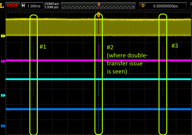
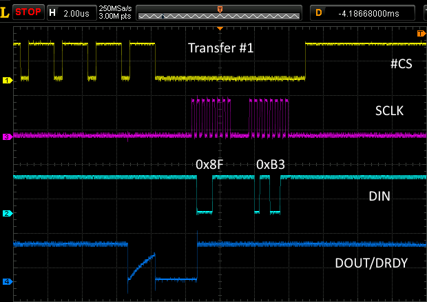
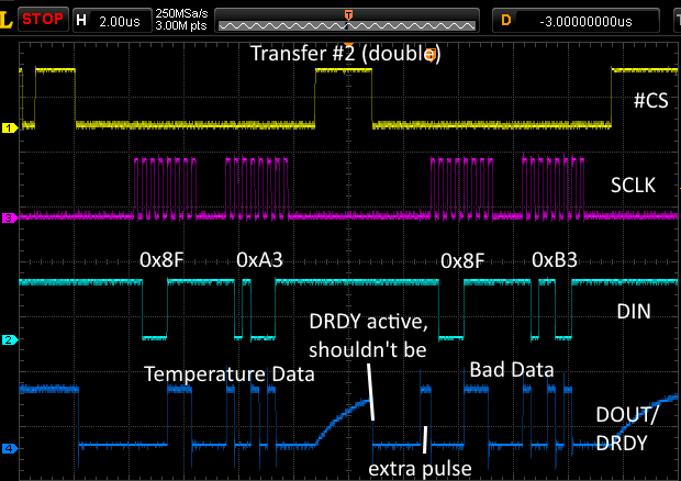
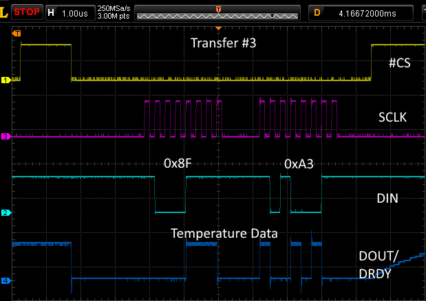
The issue I'm seeing is when switching inputs and starting a new conversion, following which I'm polling nDRDY to see when the conversion is complete. Intermittently (maybe 1 in 10 samples) the ADS1118, following #CS going low, will indicate that a new result is ready when only ~2us have passed (running at 128SPS, this is *much* quicker than a result could actually be ready.) As well, when this happens the data result retrieved for the new conversion exactly matches the previous conversion, again confirming that another conversion was not actually run. Below is a screenshot of the SPI interface showing this issue occurring:

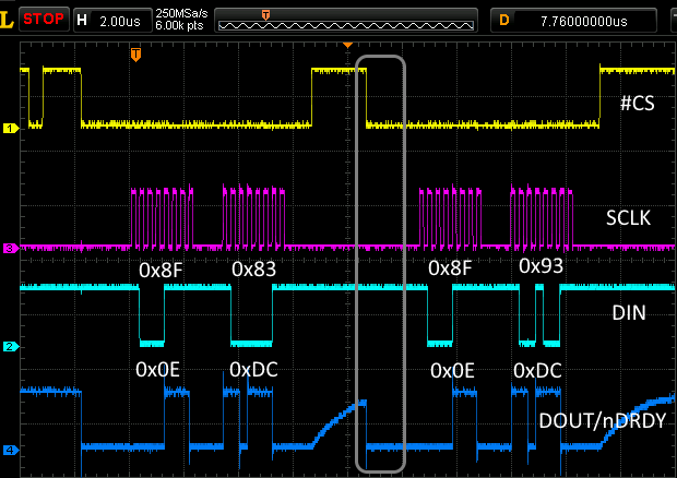
The issue is in the grey circle, where nDRDY goes low with #CS indicating that a new sample is ready, when it obviously isn't.

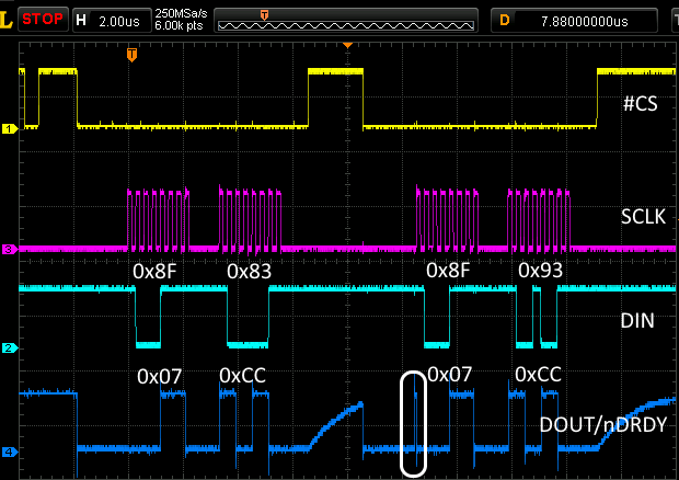
Interestingly, in the exact same failures I've noticed that sometimes the nDRDY signal will appear to respond following #CS going low and prior to the first edge on SCLK, this is shown circled here:

And shown in more detail here:

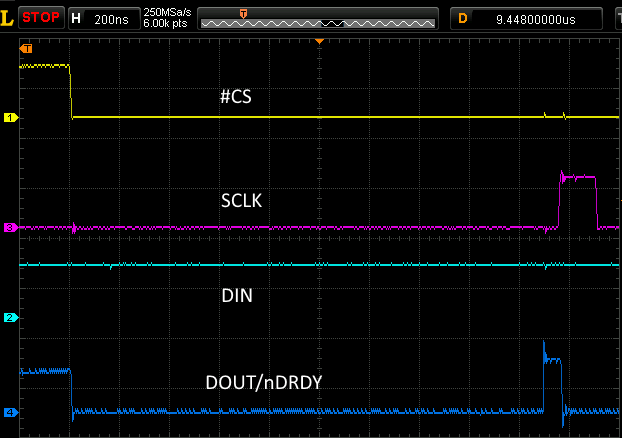
It looks like the ADS1118 might be trying to indicate that a sample isn't ready, but it has already pulled nDRDY low for ~2us, much much longer than the t(CSDOD) spec of 100ns in the datasheet.

I'm at a loss to explain this behaviour as all timing specifications seem to be met. There seem to be no errata for this device, so I'm not sure if this is a known issue. After perusing other related questions on the ADS1118, the only interesting tidbit is a comment on a 20us delay when running in single-shot mode made by Krunal Maniar from TI here: 

I'm really interested in hearing any thoughts as to why this may be occurring, as well as any possible resolutions!

  • Cory,


    We generally don't do errata sheets and try to roll in any problems we find into datasheet revisions. That being said, I think what you're seeing is expected given specific conditions. I'll give an explanation of what I think is happening, and give something to try.

    Let's start with your first scope shot. Here it is below:


    I think what you're expecting is that DOUT/DRDY is supposed to be high when the conversion is completed when /CS returns low. However, DOUT/DRDY doesn't necessarily return high after reading back the device. Look at Figure 42 in the datasheet. At the end of retrieving the data, DOUT/DRDY can be either high or low because it retains the value of the last bit read from the device. After /CS returns high and then low once more, the DOUT/DRDY continues to retain the last bit value it had before /CS transitioned.

    Here is the second scope shot:


    I think here, the device is starting to signal that it has completed the conversion. However, you've interrupted the device. Instead of the device putting out the expected 8us pulse as shown in Figure 38 of the datasheet, you've started clocking SCLKs. The device responds with the clocking out the data on DOUT/DRDY instead of completing the pulse.

    Now, there are a couple of things that you can try.

    First, I would still run the device in single-shot mode. However, to read back the data, I would insert a delay to read back the device. If you are running at 128 SPS, start the readback after 7.81ms+10% or 8.6ms. This should ensure a new conversion result.

    Second, you could start the conversion, cycle /CS (or not) and then poll DOUT/DRDY to find the 8us pulse to determine when to read out the data. What you want to find is not the state of DOUT/DRDY, but rather the transition of DOUT/DRDY low.

    Regardless, try either or both of these things and see if they work for you. If you have problems feel free to post back.


    Joseph Wu

  • Hi Joseph,

    Thanks for the quick and detailed response, I really appreciate it! After reading your post I'm not sure I'm in total agreement about how the device is operating, at least not yet.

    Quote (JW) re: 1st screenshot:

    I think what you're expecting is that DOUT/DRDY is supposed to be high when the conversion is completed when /CS returns low. However, DOUT/DRDY doesn't necessarily return high after reading back the device. Look at Figure 42 in the datasheet. At the end of retrieving the data, DOUT/DRDY can be either high or low because it retains the value of the last bit read from the device. After /CS returns high and then low once more, the DOUT/DRDY continues to retain the last bit value it had before /CS transitioned. 

    You're right in that I expect DOUT/DRDY to statically represent the state of the conversion when in single-shot mode and prior to data transfer, this is certainly what the datasheet seems to indicate (9.5.7.2/Figure 42):

    Quote (datasheet):

    Taking CS high resets the SPI interface. The next time CS is taken low, data transmission starts with the currently buffered conversion result on the first SCLK rising edge. If DOUT/DRDY is low when data retrieval starts, the conversion buffer is already updated with a new result. Otherwise, if DOUT/DRDY is high, the same result from the previous data transmission cycle is read.

    This seems to pretty clearly state that the SPI interface is reset on /CS cycling, and that DOUT/DRDY should represent the status of the conversion when #CS is brought low. My interpretation was that the indeterminate data following /CS going low in Figure 42 is just an indication that the conversion may not have completed yet and you need to wait for it to go low before starting the data retrieval to get the new result.

    I have noticed is that this issue only occurs following a temperature measurement, which is interesting. As temperature readings are left-justfied/14-bits, the LSb of the first conversion result is always 0 as you suggest. However, this issue doesn't present itself following an ADC conversion with the LSB = 0.

    Quote (JW) re: 2nd screenshot:

    I think here, the device is starting to signal that it has completed the conversion. However, you've interrupted the device. Instead of the device putting out the expected 8us pulse as shown in Figure 38 of the datasheet, you've started clocking SCLKs. The device responds with the clocking out the data on DOUT/DRDY instead of completing the pulse.

    I think a few things here don't quite fit:

    1. This pulse occurs ~5us following the initiation of the conversion, I think it's safe to say that at 128SPS there is no chance that the conversion has completed already. I have also rerun the testing at 32SPS with the exact same results.
    2. The 8us pulse in Figure 38 only applies to continuous conversion mode, and is an indication that the previous conversion result wasn't read and that a new result has overwritten it. I don't think this applies here. I do agree that the SCLK transition interrupts this DOUT/DRDY pulse, but I'm not sure why we're seeing the pulse in the first place.
    3. The device is in the process of running a single-shot conversion on AIN0:AIN1, but is very clearly returning temperature sensor data. This is my biggest concern.

    It seems that the behaviour I'm seeing always follows a temperature conversion, but only in maybe 5 - 10% of the temperature conversions I'm doing. I have played around with the timing and delays and I can get it working on the bench consistently, but I need to feel more comfortable with this issue and why it's happening before committing to thousands of units in production.

    Thanks again for your help!

    Cory

  • Just wanted to add a note that the temperature measurement was a red herring. I was performing a number of calculations following the analog measurement which added enough delay that /DRDY was never mis-sampled. Removing those delays shows this issue occurring after both temperature measurements and analog measurements (including those where the LSb = 1, which I wasn't able to confirm before).

    Cory
  • Cory,

    I read through your previous posts. Let me address the comments on the 2nd scope shot first, and then I'll get back to the comment on the datasheet. I'll reference two of your quotes in red.

    1. This pulse occurs ~5us following the initiation of the conversion, I think it's safe to say that at 128SPS there is no chance that the conversion has completed already. I have also rerun the testing at 32SPS with the exact same results.

    The problem is that I'm not sure where the conversion actually started. It looks like you are issuing the conversion start for each communication with the device. Every communication has a 1 in the MSB of the configuration register.

    In single-shot mode, when the device has already started a conversion, an new conversion start does not interrupt the conversion. The device simply waits until the conversion completes and holds that command in a buffer. When the conversion completes, it will make the change in the configuration register and start a new conversion. So if you're giving multiple start conversions, the conversion probably started well before this scope shot. If you only want to read back the device, make sure the MSB of the configuration register is a 0.

    2. The 8us pulse in Figure 38 only applies to continuous conversion mode, and is an indication that the previous conversion result wasn't read and that a new result has overwritten it. I don't think this applies here. I do agree that the SCLK transition interrupts this DOUT/DRDY pulse, but I'm not sure why we're seeing the pulse in the first place.

    I'm pretty sure that the DOUT/DRDY behavior isn't different between the continuous conversion mode and single-shot mode. I think that the figure title is written as continuous conversion mode because that's the mode applicable case for using it.

    Going back to your other comment about the 1st scope shot, you're correct about what it says in the datasheet about the DOUT/DRDY having a new conversion result and being low when /CS returns low. The way it is written, certainly supports your interpretation of it. However, I'll need to check into this, because I'm not sure how this changes DOUT/DRDY if another conversion in being held ready to go when there's another conversion.

    If you have the opportunity, I would make two changes to the read out. First use the 32-bit data transmission cycle to read back the device. It should force DOUT/DRDY high after the read as shown in Figure 40 and 41. Second, I would make sure that another single-shot conversion isn't started until after the current conversion has completed. Even if you do use the 32-bit transmission cycle. Check the status of DOUT/DRDY after /CS has returned low before trying to write a conversion start to the configuration register again.

    Joseph Wu

  • Joseph,

    Thanks again for your help in trying to narrow this issue down. I'll reference your quotes in blue to try and keep things easy to follow.

    1. (JW) The problem is that I'm not sure where the conversion actually started. It looks like you are issuing the conversion start for each communication with the device. Every communication has a 1 in the MSB of the configuration register.

    I am indeed issuing a start command during each communication with the device. The basic control flow is:

    a. Issue Start Command on Temperature/Discard Data

    b. Poll DOUT/DRDY until LOW

    c. Issue Start Command on AIN0:AIN1/Retrieve  Temperature Data during same data transfer.

    d. Poll DOUT/DRDY until LOW

    e. Issue Start Command on Temperature/ Retrieve AIN0:AIN1 Data during same data transfer.

    f. Poll DOUT/DRDY until Low

    g. Repeat c - f forever

    As you can see, each communication with the device (aside from the initial on startup) retrieves the previous conversion result and starts the next conversion. I'm not (at least as far as I can tell) initiating another conversion when the previous one hasn't completed. No Start command is issued without verifying that the DOUT/DRDY line is LOW.

    2. (JW)I'm pretty sure that the DOUT/DRDY behavior isn't different between the continuous conversion mode and single-shot mode. I think that the figure title is written as continuous conversion mode because that's the mode applicable case for using it.

    My impression is that the DOUT/DRDY behaviour is different in single-shot vs continuous mode, though maybe I'm mistaken. From the datasheet (9.5.5):

    In continuous-conversion mode, DOUT/DRDY transitions high again 8 µs before the next data ready signal (DOUT/DRDY low) if no data are retrieved from the device. This transition is shown in Figure 38. 

    From this description it sounds to me like the 8 us pulse will never happen in single-shot mode, because you can never have the conversion result overwritten by a subsequent conversion. Each time I start a conversion I'm reading the previous result so there is no chance of a result buffer being overrun.

    3. (JW)First use the 32-bit data transmission cycle to read back the device. It should force DOUT/DRDY high after the read as shown in Figure 40 and 41.

    I have done this previously, and it does fix the issue, at least on the bench. In fact, any delay of ~5us following the 16-bit data transfer fixes the issue as well, so I don't think it has anything to do with the state of the data lines but rather the timing of the SPI interface. My concern as always is that this fix works on the bench, but I'd really like to know what's going to be confident that I won't have devices failing in the field if for example they're operating at 85degC and the timing changes and all of a sudden the issue reappears.

    4. (JW)Second, I would make sure that another single-shot conversion isn't started until after the current conversion has completed. Even if you do use the 32-bit transmission cycle. Check the status of DOUT/DRDY after /CS has returned low before trying to write a conversion start to the configuration register again.

    This is currently being done. No conversions are started without the previous one being completed (i.e., being indicated as completed by the DOUT/DRDY line being held low).

    The issue remains that the DOUT/DRDY line is being held low after /CS is brought low, when the conversion has obviously not completed.

    Thanks for all of your help with this!

    Cory

  • Joseph,

    I'll include a few quick screenshots here that will hopefully cover what we've discussed:

    This is a sequence of 3 transfers that occur during my operation of the ADS1118. Data rate is set at 250SPS and samples are seen to occur at ~4ms intervals as expected. DRDY sampling seen on /CS works well 99.9% of the time:

    Transfer #1 is a retrieval of AIN1:AIN0 data as shown here (full scale result 0x7FFF) and a command to start conversion on the temperature channel:

    Transfer #2 is where I'm seeing the issue with DRDY being pulled low incorrectly:

    The first transfer pulls data from the temperature channel and starts a conversion on AIN1:AIN0. /CS is deactivated to reset the SPI interface, then asserted again to poll DRDY which (incorrectly) indicates that the conversion is complete. Instead of reading AIN1:AIN0 data I'm reading the temperature data again and my data buffers are corrupted.

    Transfer #3 again reads temperature data as shown here:

    Again, this double transfer issue I'm seeing only occurs in maybe 5 - 10% of AIN0:AIN1 readings, and not consistently.

    Cory

  • Cory,


    Sorry I didn't get back to you on this yesterday. There were a couple of other things that came up. It did give me a chance to think about this question though.

    One comment that you made was this:

    "I have done this previously, and it does fix the issue, at least on the bench. In fact, any delay of ~5us following the 16-bit data transfer fixes the issue as well, so I don't think it has anything to do with the state of the data lines but rather the timing of the SPI interface. My concern as always is that this fix works on the bench, but I'd really like to know what's going to be confident that I won't have devices failing in the field if for example they're operating at 85degC and the timing changes and all of a sudden the issue reappears."

    If ~5us of delay fixes this problem, then I would extend this to 20us as a fix. Here's what I think is the issue. When you start a conversion in single-shot mode, the conversion will complete and then shut down the device. At that point, the analog section and oscillator is powered down and the digital isn't being clocked.

    When you read this back to start a new conversion in 16-bit readback mode, you start a new conversion, but that doesn't get translated until 1. the 16-bit configuration register is completely written, and 2. the device has powered back up and the oscillator has started up again.

    When you check DOUT/DRDY 5us after the device has been read back, the device probably hasn't powered up again. There's no SCLK or internal clock to move DOUT/DRDY back high. Normally, I would say wait 20us (accounting for changes in process and temperature) for the device to power itself up again before checking DOUT/DRDY.

    Give that a try and see if that works for you.


    Joseph Wu
  • Cory,


    Out of curiosity, did my last post help solve your problem? I just wanted to make sure you got a solution to your DRDY/DOUT error. I'll close this post for now, but if you want to continue to ask questions, you can add on to this post, or contribute a new post if you get locked out.


    Joseph Wu
  • Hi Joseph,

    Sorry for the falling off the face of the earth, I had closed that task up and forgot to reply. While I'm not totally comfortable with the solution you proposed, it's what I've had to do in the end.

    When you check DOUT/DRDY 5us after the device has been read back, the device probably hasn't powered up again. There's no SCLK or internal clock to move DOUT/DRDY back high. Normally, I would say wait 20us (accounting for changes in process and temperature) for the device to power itself up again before checking DOUT/DRDY.

    My concern was always that the datasheet specifies no delay time for checking /DRDY and the 20us delay is kind of a finger in the wind. Really, the device doesn't seem to be operating to spec which is always concerning. In this application at least it's not a difficult hack to add the delay and I'm hopeful there is enough margin in there to avoid any issues.

    Thank you very much for all the help you have provided, it's really appreciated!

    Regards,

    Cory

  • Cory,


    Thanks for getting back to me. I understand your concern about the added delay, and how the DOUT/DRDY line doesn't show the proper output while the device is powering back on. I'll check and see if we can make a datasheet change to make this more clear.

    Regardless, thanks for the question. If you have any other questions, please feel free to start a new post.


    Joseph Wu