


Part Number: ADS1292
Other Parts Discussed in Thread: ADS130E08
Hello,
I am developing pcb board with ADS1292 and I am having issues with receiving data from ADS.
Firstly, here's my ads schematic:
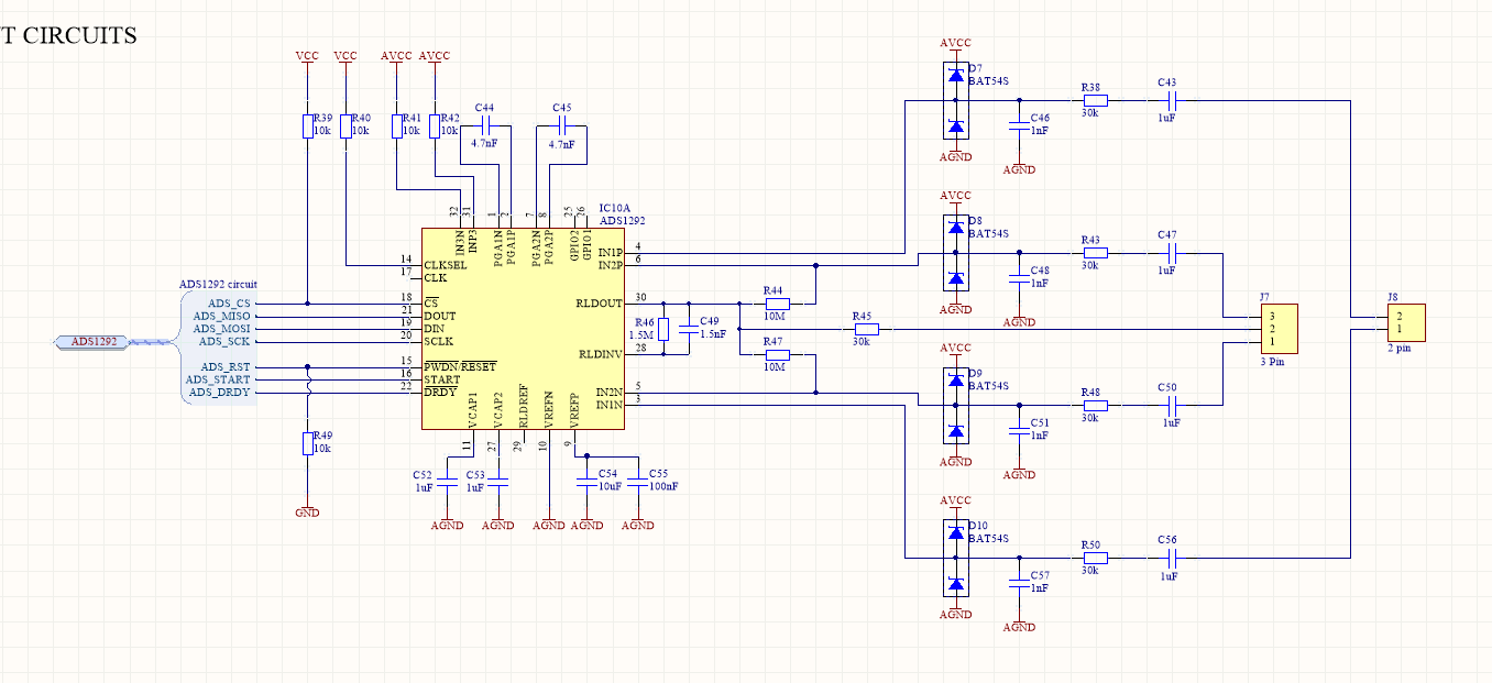
Both Voltages (VCC and AVCC are 3.3V).
I would like to use ADS1292 in 2 electrode configuration (that means without external RLD) , however I added both channels on pcb, because it's prototype and i wanted to test this chip.
Problem is, i can get it to work in any configuration I try (despite channel i chose). Is there anything particularly wrong in this schematic?
My software on STM board waits for DRDY signal and then reads 9 bytes of data. I try to read 15k samples (with 125SPS rate).
My problem is, chip acts kind of strangely. Sometimes it will read just a few samples (let's say up to 150), sometimes it won't even read 10 samples, and sometime's it will read everything (in that case, mostly zeros).
Thing that I would love to add is that I am successfully reading / writing registers or sending commands to ADS.
This are my registers settings:
REG_CONFIG1, 0x00
CONFIG2, 0xA0
CH1SET, 0x81
REG_CH2SET, 0x60
RESP2, 0x07
RLD_SENS, 0x20
LOFF, 0x11
REG_LOFF_SENS, 0x00
LOFF_STAT, 0x10
RESP1, 0x02
GPIO, 0x0C
I hope I provided enough information!
Thank you in advance for help!
@Update:
Quick update, I managed to find out, that chip resets during data reading, because if I am able to receive 15k samples, the values of registers (checked after data reading) are different (they match reset values form datasheet p.39)


