This thread has been locked.

If you have a related question, please click the "Ask a related question" button in the top right corner. The newly created question will be automatically linked to this question.

ADS130E08: SPI Comms stop after few DATA_Ready triggers

Part Number: ADS130E08
Other Parts Discussed in Thread: ADS131E08

I have the AD130E08 setup to provide continuous conversion by setting it in continuous reading so Data_Ready goes low at  8 ksamples/s. 

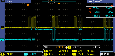
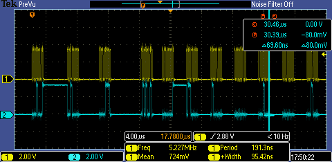
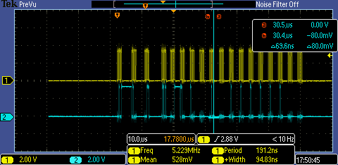
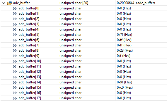
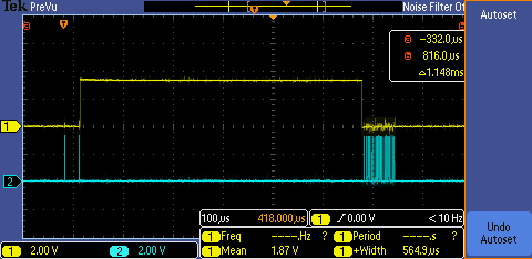
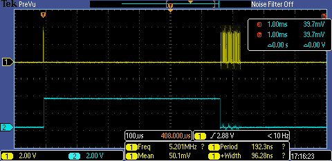
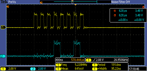
When I initialized the SPI driver, I can start reading 152 bits (19 bytes) few times (maybe 5 or 6) and then Data Ready does not transition to low level to indicate a new data sample is ready.

Because it is on continuous mode, not sure what could be the reason of stopping. Any ideas?

  • Hi Jean Paul,

    Since you've not told us what your scope traces represent, I'll take a guess and say that the blue trace is DRDY and the white trace represents you reading 19 bytes of data. Is that the case? One thing to keep in mind is that if you are running the ADS131E08 at 8 kSPS, you would ideally be reading all the data out of the device at the same (or faster) rate, taking all 19 bytes of data between the DRDY pulses. It's tough to know exactly what might have happened in this case to cause the DRDY to stop, but you should be able to go in and read the register contents to see if something got corrupted during your data read cycle.
  • Tom

    Thats correct, the scope signals are Data Ready and the SCK from the SPI interface. all the SPI packets have the same Status bits 0xC0 0x00 0x00 meaning there is no fault on the ADC channels.

    Also I am reading at a very fast rate so there is sometime between the 19 bytes read and the next Data Ready event.

    Which register do you suggest me to check/read in order to investigate why the data ready stops of "interrupting" or generating an event.
  • I was able to read the registers and I notice the CONFIG3 value is not the default one which should be 0x40, Sometimes I get 0x41 or 0x80

  • Interesting... Bit 0 in the CONFIG3 register could read back as 0 or 1, so that's not too much of a surprise. Reading back 80 is strange though, since Bit 6 should always read back as a '1'. Hardware wise, how do you manage the START pin?
  • I reset the device for 1 second and then set Start pin to High. It comes directly from the MCU 3.3V output

  • Hi Jean-Paul,

    In the string above with your register reads, if the 0x80 entry is CONFIG3, is the 0x01 entry CONFIG1? That should be at least 0x91 - the CONFIG2 register seems off as well. Can you send along another screen shot zooming in on just one or two of those transfers? Can you also send the portion of your schematic around the ADS131E08?
  • I am attaching the requested screenshots. During the Reads, sometimes I only read zeros for the 19 bytes but sometimes I do read the proper data. Do you think I am reading too fast? My delay between CS and SCK is 1 us currently.

  • Hi Jean Paul,

    Thank you for the screen shots and schematic snippet. I don't see anything in the schematic that looks out of place necessarily. One thing I would question though, is how you are generating AVDD and AVSS. Those two supplies should share a common ground which would be considered analog ground (AGND), which would then tie back to your DGND. If those supplies are 'floating' with respect to your DGND, that might be the issue. Also, the four NC pins should be left floating.

    The screen shots of the SPI transfer look clean, so I'm not sure what the deal is with your data being off. It looks to me like the the data is getting rotated around to some extent. In the three array captures, the first one has 0xC0 in adc_buffer[15] - is that coincidence or is that the status byte? The third buffer detail looks right if you have the bulk of the inputs tied to FS+.
  •  Tom

    I removed the resistors from the NC pins and also I started requested manual reads every 2ms. The data is not corrupted most of the time but I am still loosing the data ready trigger. I am attaching a snapshot. I am sending a STOP command wait 2 us then a START command and then I wait for the Data Ready signal. In the picture, when it is working it shows the SPI CLK and Data Ready.

    Any other suggestion to try? should I modify the default values of the registers? I am using the default values currently.

  • Hi Jean Paul,

    Using the default settings is fine. Something in that screen capture looks off to me though. If that is SPI CLK and DRDY - what are the two pulses to the left? If you take a look at Figure 31 in the datasheet, DRDY should go HIGH after you send the START command. After the tSETTLE time, DRDY should go low, which is the point where you should start reading the conversion results. If you refer to Figure 35 now, DRDY should return high after it gets the first SCLK. If you are reading data on the left side of your capture, I would expect DRDY to have gone back to its high state there.
  • Tom

    I confirmed and it looks like Data Ready it is not behaving as it should be. Please see the attached screenshots where I plot SCK (SPI) and Data Ready, Also the START and Read Command followed by the 19 bytes Read sequence.  Read Command I verified it is 0x12h.

    Also I plot the CS line (cyan) in some screenshots. but Like you said I was expecting Data Ready goes High after the first SCK , it shoud be the first SCK during the Read Command? or the 19 bytes Read sequence?

    Start Request and then Data Ready goes low and stays low after the Read Command and 19 bytes Read Sequence.

    Read Command(0x12)

    Read Command, followed by 19 bytes read. CS line included(cyan)

  • Hi Jean Paul,

    Do you have another board you can work with? Perhaps this device is somehow damaged. One other thing, it almost looks like there is some activity on the /CS line - you can see faint traces, which I can't tell if they are real or an artifact of your scope. If they are real - that might be part of the problem. The /CS line has to stay low through the entire data retrieval process. You should also consider using RDATAC mode and you would not need to issue the RDATA command at all.
  • Thanks Tom, I will verify, but it could the scope. What about the Data Ready signal, is that the expected behavior? I will see if I can replace the chip at this point in my board.

  • No - best I can tell, DRDY went low just ahead of /CS so it looks like you are waiting the appropriate settling time. DRDY should have gone high with the SCLK that started your RDATA command.