This thread has been locked.

If you have a related question, please click the "Ask a related question" button in the top right corner. The newly created question will be automatically linked to this question.

ADS1292R: Single Shot Mode

Part Number: ADS1292R
Other Parts Discussed in Thread: ADS1292

Hi Team,

Good afternoon, my customer is using the ADS1292R and DRDY isn't asserting in single shot mode (either through the START pin or command). When switching over to continuous mode there is no issues.

Similar to the issues in this post:

https://e2e.ti.com/support/data_converters/precision_data_converters/f/73/p/542243/1980216#pi318173=2

Information from the customer:

For reference, here is the ADS1292 register dump after I complete my setup.  I am using a 512kHz external clock (CLK_SEL pin  = 0).  However I have also tried using the internal 512kHz clock with the same results (I prefer using the internal clock if possible).


ADDR:00 01 02 03 04 05 06 07 08 09 0A 0B 

DATA:73 86 A0 10 81 60 2C 00 00 00 01 0C


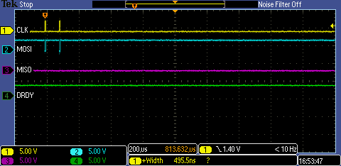
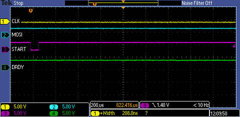
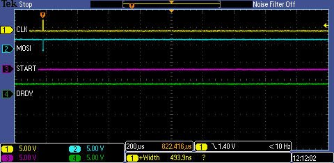
Here is a screenshot showing no DRDY following START toggle.  START is low for about 70us.  No DRDY for at least 1.5ms.

Here is a screenshot showing no DRDY following a START command for at least 1.5ms.


Thank you and please let me know if you have any questions.

Regards,

~John

  • Hi John,

    Thanks for posting their question!

    On power-up, the ADS1292R will start in Continuous Conversion Mode by default. When switching to Single-Shot Mode, I found a recommendation in the datasheet to toggle the START pin:

    "When switching from continuous mode to pulse mode, make sure the START signal is pulsed or issue a STOP command followed by a START command."

    Give this a try first and let me know if that works.

    On a side note, I reviewed all the register settings and found a slight mistake. RESP1 (0x09) cannot be set to 0x00 as Bit 1 must always be '1'. Please write 0x02 to this register.

    Best Regards,

  • Hi Ryan,

    Thank you for the quick response - unfortunately that didn't fix the issue:

    Here is my new register dump.  I am now programming RESP1 to 0x02.  I was not programming it at all before.  The POR default was simply 0x00.

    ADDR:00 01 02 03 04 05 06 07 08 09 0A 0B 

    DATA:73 86 A0 10 81 60 2C 00 00 02 01 0C


    I added a STOP command in front of every START command with ~80us of delay between them.  Still no DRDY assertions.


    Here it is zoomed in...you can just makeout the 0x0A (STOP) and 0x08 (START) on the MOSI output.

    Any other thoughts on what could be causing this?

    Regards,

    ~John

  • Hi John,

    The customer does not need to send the STOP command every time, only once after changing the CONFIG1 register to use "Single-Shot Mode."

    /DRDY should pulse low after the settling time (tSETTLE) is completed. For DR[2:0] = 110, tSETTLE = 68*tMOD, where the modulator frequency is 128 kHz. Therefore, tSETTLE equals 531.25 us, which is certainly less time than what your customer has been waiting for.

    Can you send us a schematic capture to show the connections to the ADS1292R?

    Also, please send an SPI capture showing /CS, SCLK, MOSI, and /DRDY during one of the SPI command transactions so that we can verify that all timing requirements are met.

    Best Regards,
  • Hi Ryan,

    Here is the scope shot:

    Here is a zoomed in look at the START command on the SPI bus.  The CS# line is not shown -- it is simply tied to GND.  However I have also tried manually wiring the CS# to my micro and toggling it with each SPI transaction.  It doesn't seem to make any difference.  Also, for this test case I am holding the START signal low.  Note that my SPI clock rate is set to 1MHz in my micro.  And also that the SPI bus appears to be working for me during register reads/writes and during continuous mode.

    Regards,

    ~John

  • Hi John,

    Thanks for the updates. I'll need to discuss this with a designer and get back to you. Thanks for your patience.

    Regards,
  • Hi John,

    Following our discussions offline, the issue was apparently related to using the OFFSETCAL command during their start-up sequence. The OFFSETCAL command will tell the device to complete a series of conversions internally and store the average result. In order to do this:

    1. The START pin must remain high throughout the process, or the START command must be sent prior to sending the OFFSETCAL command.
    2. The device must be in Continuous Conversion Mode. After the OFFSETCAL sequence has completed (indicated by new /DRDY falling edges), the user can place the device into Single-Shot Mode.

    Best Regards,

  • Hi Ryan,

    Thank you for your help on this!

    The one other note I had on the offsetcal was to keep the bit (RESP2[7]) enabled after the calibration is complete.

    Regards,
    ~John