This thread has been locked.

If you have a related question, please click the "Ask a related question" button in the top right corner. The newly created question will be automatically linked to this question.

TLV2548: The TLV2548 ch0 output datas when they are bigger than certain voltage,it will be lower

Part Number: TLV2548

Hi All,

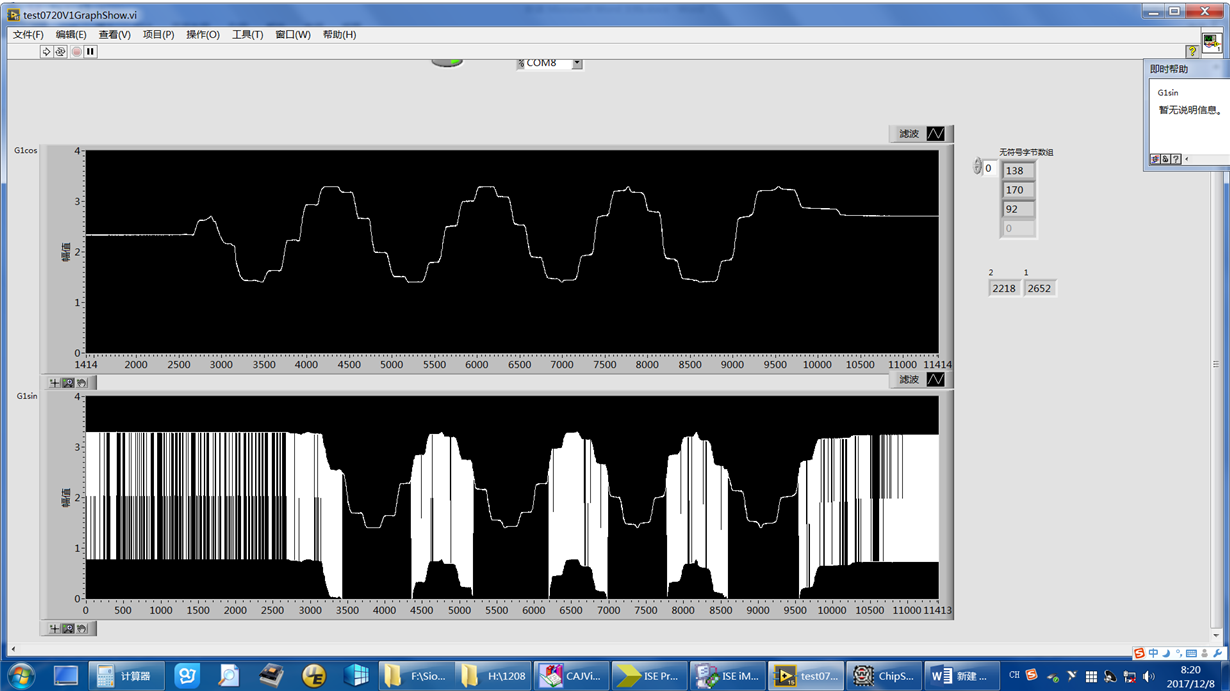
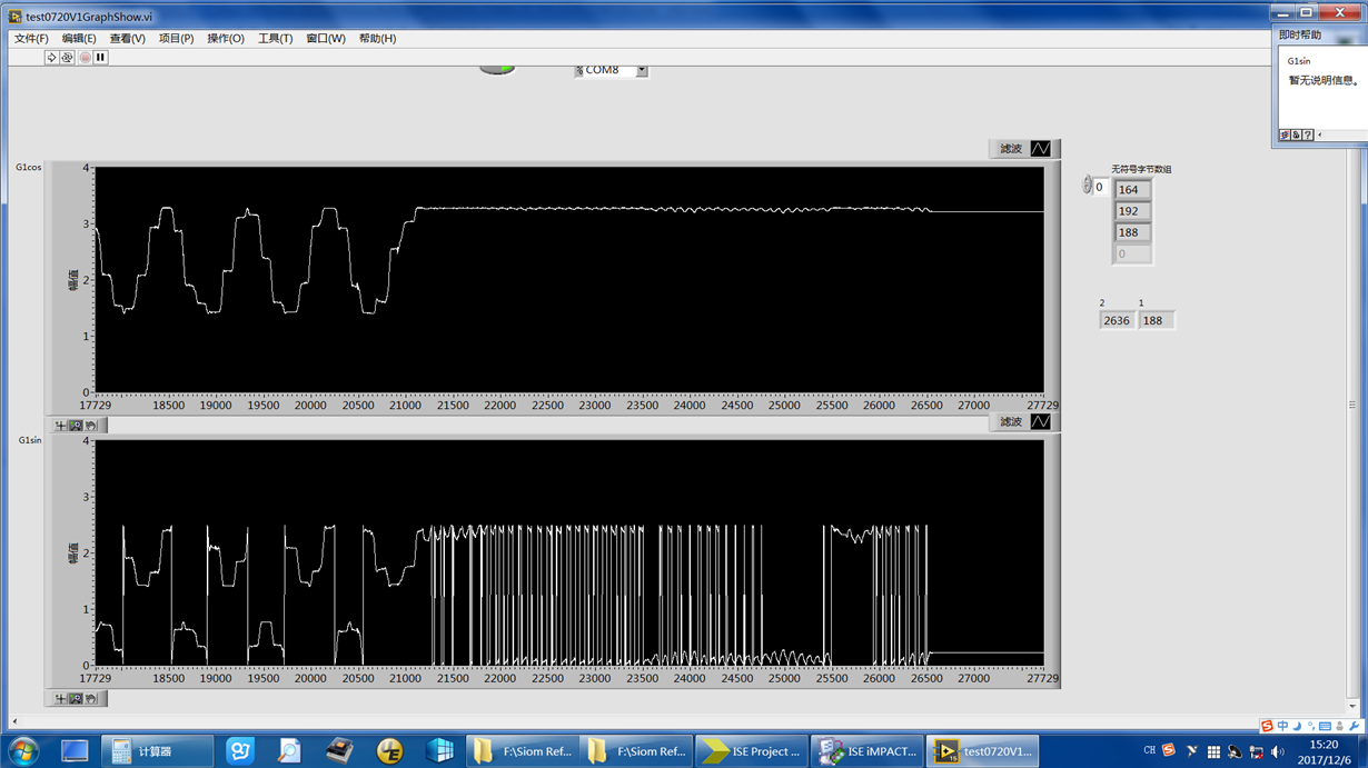
      I lately use TLV2548 to get the Sin and Cos signals. The ch2 is used to achive Cos, and the getted signal is right.But the Sin signal is not right, which is getted by ch0. As show below,when the signal is bigger than some voltage, it will jump down, I am really  distressed.Why the  voltage jump down, and can not hold up???
  • Hello,

    If I understand correctly, you have a cosine signal on the channel 2 input and a sine signal on the channel 0 input.  Does the picture you provided show a graph of the codes from the TLV2548?

    Some additional information is needed.

    What supply voltage are you using?

    What voltage is on REFP and REFM?

    What do the signals on the input pins of channel 0 and 2 look like on an oscilloscope?

    What frequency are the input signal at?

    Mike

  • Hi,
    I use 5v spply it,and REAM-REAP is 5V. I test it again,give ch0 3v and 2.5v,the output SDO lost the D11,it always be 0,can not be 1. I get SDO from chipscope.
  • Hello,

    So you have:
    Vcc = 5V
    REFP = 5V
    REFM = Ground
    Ch0 = a DC voltage of either 3V or 2.5V.

    Is that correct?

    What value are you sending to the configuration register?

    Please post a scope shot showing CS, SDI, SDO and SCLK.

    Mike
  • Hi,

    Thanks to reply me. Here is my order scope, 

    My order is 1010000011011011,my SCLK is 10M.The ch2 is right, but the ch0 the MSB is lost when it should be ‘1’. Like this 

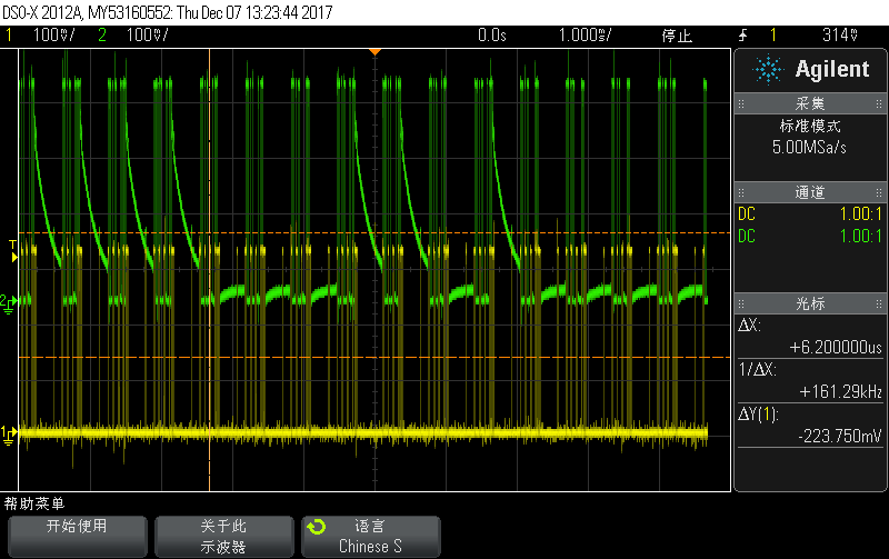
    And below is chipscope from oscillograph 

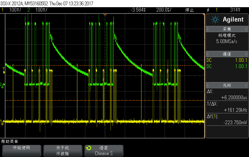
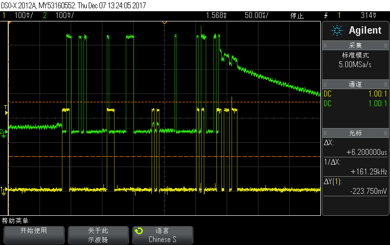
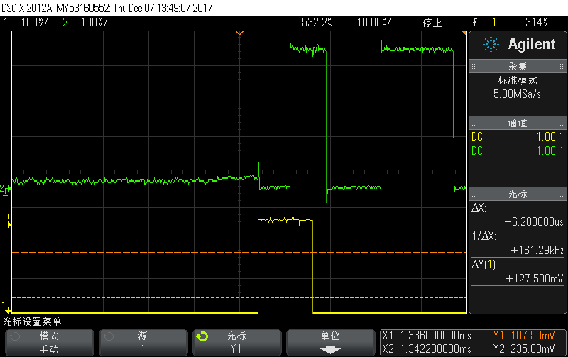
    Yellow is SDI, green is SDO,I find that when slope the data is right, when it is low the data is wrong.The datas some time right sometime wrong

    Below is the right data.

    And below is the wrong datas

    below is the enlarded picure

    And there have a little sharp, but is not high level.

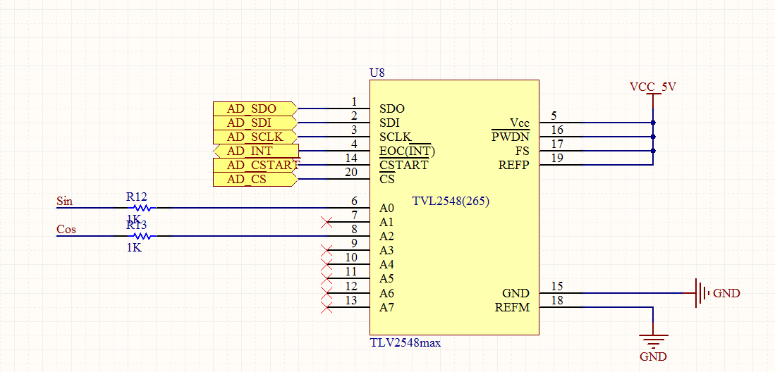
    Below is the circuit

    Do you find the problems? I am looking forward your reply!

  • In roder to test the input is 3.0VDC,is not the sin snd cos
  • Hello,

    Something you can try to troubleshoot is to make sure that you are getting correct values for each channel.

    Do do this put it in single shot mode CFR = 1010 0000 1001 1011 (note D4,3 and D1,0 will not take affect in this mode). Put DC 3V on CH0. Then write 0000 repeatedly to read channel 0. You should get a value close to 1001 1001 1001 (as long as you input of 3V and the reference of 5V are accurate). Next try the same on channel 2. Put DC 3V on CH2. Then write 0010 repeatedly to read channel 2. You should get close to the same value. This will show that inputs are good and you are able to read channels 0 and 2 correctly.

    Mike