This thread has been locked.

If you have a related question, please click the "Ask a related question" button in the top right corner. The newly created question will be automatically linked to this question.

ADS1194: RLD feedback loop

Part Number: ADS1194
Other Parts Discussed in Thread: ADS1298

Hi,

We are trying to design a 6 leads ECG with 4 electrodes + 1 RLD electrode with your ADS1194.

In our design, we connected :

RA-LA to channel 1

RA-LL to channel 2

RA-V1 to channel 3

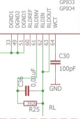
RLD electrode to RLD_IN, RLD_OUT.  And RLD_INV through a 0.01 uF cap and a 392 kOhm resistor.

Then I set the CONFIG3 register to :1101 1100

PD_REFBUF enable

VREF 2.4V

RLD_MEAS RLD_IN routed to channel 3

RLDREF feed internally

RLD BUFFER enabled

RLD LO SENSE disabled

RLD connected

But then I still have strong common mode interferences that typically are as high as the R peak. And connecting, disconnecting the RL electrode doesn't change anything suggesting that the RLD drive doesn't work.

Is there something I did wrong regardind the electronic design, the registers ?

Thanks in advance,

Grégoire

  • Hello Gregoire,

    Welcome to our forum!

    There are a couple things you might try to improve the rejection of common-mode interference. First, increase the closed-loop bandwidth of the RLD amplifier. Unfortunately, our existing ADS1298 EVM does not show a good example here (I assume that's where you got the 392k || 0.01 uF). The closed-loop bandwidth with those components is set to 40.6 Hz. Since this amplifier is passing through the common-mode cancellation signal to the body, we want to include 50-Hz/60-Hz noise. Try increasing the cutoff frequency to about 100 Hz / 120 Hz (i.e. 1 M || 1.2 nF gives you 132 Hz).

    Second, adjust the RLD_SENS settings. This register is used to select individual PGA outputs for RLD derivation. Usually, the PGA outputs corresponding to one or more of the primary electrodes are selected (i.e. PGA1P (RA), PGA1N (LA), PGA2N (LL) in your case). Without selecting anything, the RLD amplifier is only driving a buffered mid-supply DC voltage to the body and is not effective in cancelling common-mode noise.

    Best Regards,

  • Hi Ryan,

    Thanks for this very quick answer. I'll try to change the registers and the filter values.
    I noticed we usually get harmonics that are high as well (especially 50/3 Hz and 50*3 Hz), should I expect them to be attenuated by the RLD ? If yes, I should increase the cutoff to >150 Hz or is there a risk of having a too high cutoff freq ?

    I'll keep you updated on the results of the tests.

    Thanks,

    Greg