This thread has been locked.

If you have a related question, please click the "Ask a related question" button in the top right corner. The newly created question will be automatically linked to this question.

ADS122C04: Sawtooth noise on shorted input

Part Number: ADS122C04

Hello,

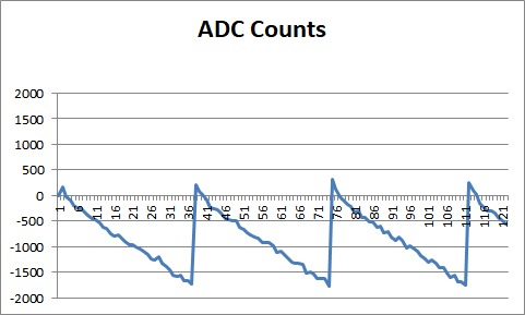
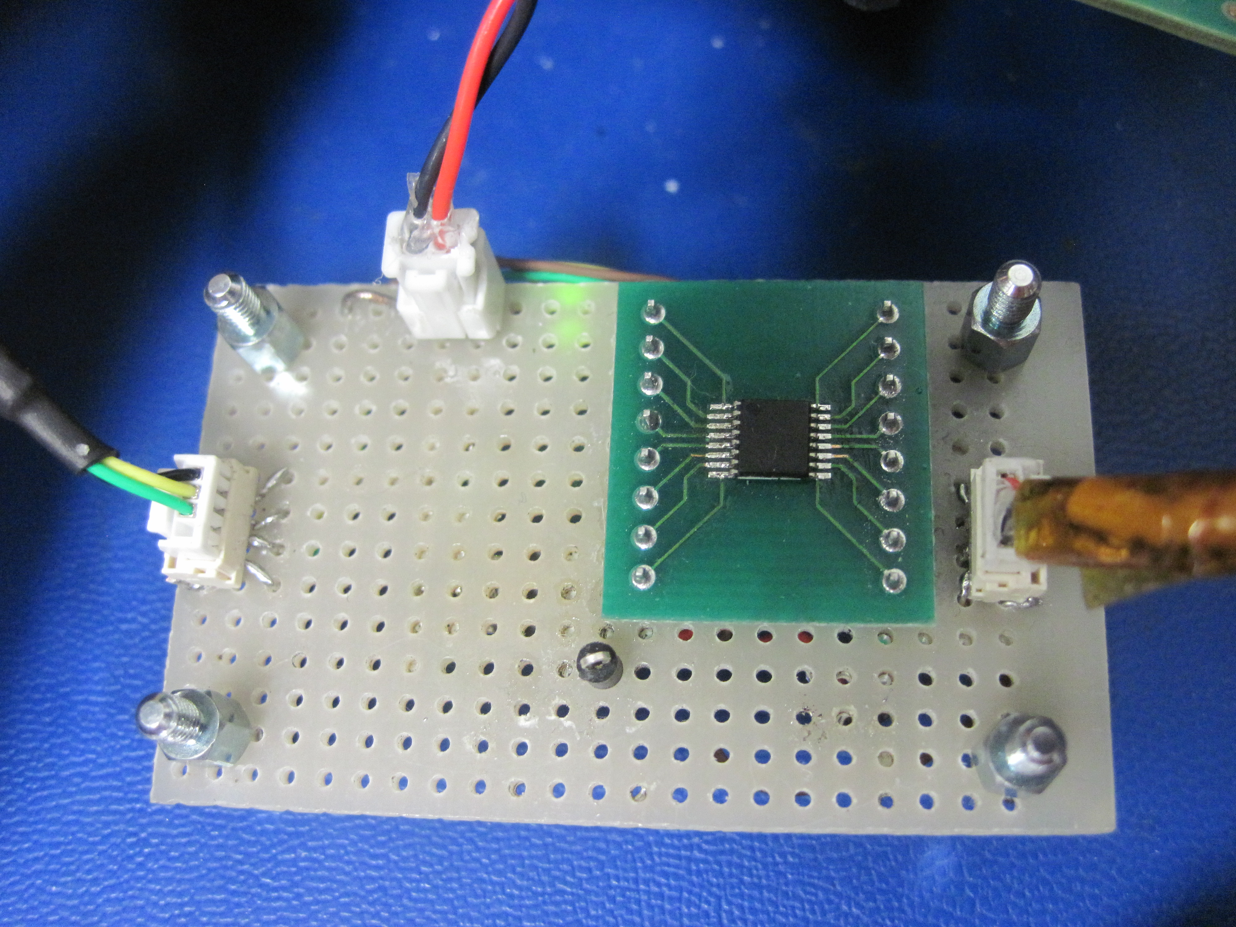
I am prototyping on perfboard with this ADC, and am experiencing a ~2Hz sawtooth noise in my data. (Plot below)
With the input pins shorted at the ADC, the noise goes away.
With an RC filter at the input, and shorted on the far side of the Rf1/Rf2, the noise appears.
Reducing the series resistors by one order of magnitude reduces the noise proportionally.
This leads me to suspect the input pins are sourcing/sinking more current than expected.

If instead this noise were aliased high-frequency content (2Hz from Fmod at 512kHz) I would have expected increasing the RC filter cutoff frequency from 900Hz to 9kHz would have increased the noise, rather than decreasing it - so I don't think it's this. I'm not aware of other possibilities.

DVdd=3V3
AVdd=5.000V
PGA: Enabled. Gain=128
Refp/n: AVdd
Input: AIN0/AIN1
Therefore input full scale = ±39mV

DRDY: Floating
/RESET: DVdd
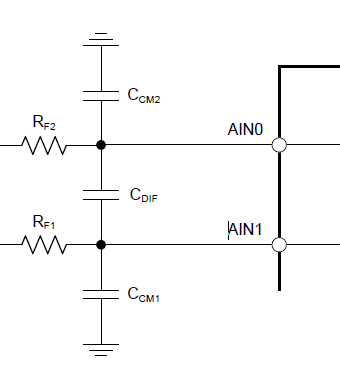
RC filter: Similar to recommended on page 44 of datasheet:
Rf1=Rf2=1k Cdif=0.1uF Ccm1=Ccm2=1nf
Filter caps C0G


Bypass caps X7R 0.1uF on DVdd and AVdd.
Output rate: 90Hz
Turbo mode enabled
Continuous sampling enabled


Sawtooth noise: 1900 counts, or 9uV pk-pk at AIN0/AIN1
Apparent differential input current = 9uV / 1k = 9nA.
Datasheet: says input current is  ±1nA on pg.5 (since PGA enabled with Gain=128)

I tried measuring the actual noise signal, but my 6 digit bench multimeter is a little too noisy down at this low voltage, so I can't verify the voltage at the input pins.

  • Hi William,

    Welcome to the forum.  You say you have the inputs shorted.  What is the common-mode of the short? This should be (AVDD+AVSS)/2 which is 2.5V for your setup.  This can be accomplished by using a simple voltage divider.  The input current specification is based on the input shorted to mid-supply as opposed to just a simple short.

    If the input is shorted to AVDD or AVSS, this can also present an issue as the PGA will be outside the normal operating range,

    I do find that the cyclic nature is interesting.  This is more often related to drift and fans turning on an off or possibly a vibration.  It would seem that the resistors have some effect, but it is difficult to guess what that affect is without knowing more about the input common-mode and device setup.  As this is a prototyping system, can you send a picture of the setup for me to look at?

    Have you tried other modes of operation like 90sps normal mode, or with PGA disabled?

    Best regards,

    Bob B

  • Thanks Bob.

    I am using a 350 ohm resistor bridge as a load cell simulator. I use it and a jumper to apply the the short across the sense wires, which are therefore both at 2.5V as you suggest.

    I have encountered other cyclic issues in the past, and have eliminated other sources of noise as much as possible (i.e. turning motors off, running ADC in an ESD bag). Certainly nothing should be in this frequency range, or with this waveform.

    I haven't exhaustively tried the other modes, but I have tried 90sps normal. (I switched to turbo hoping this would go away).

    With the PGA bypassed and a gain of 4 set (via switched-capacitor) I see only random noise (100±20 counts) instead of the sawtooth.

    I just repeated this test at several different gains, with and without the PGA. Now I can no longer recreate the issue under original conditions - despite having been experimenting and quantifying it for two days, where it has been unceasing.

    I wonder if disabling and re-enabling the PGA somehow cleared the fault, because it is enabled by default. Seems hard to believe.

    Anyways here is the prototype. REFP/REFN connections are Kelvin connections. Inputs to ADC have minimum area; all analog wires are twisted, etc.

  • Hi William,

    I will have to give this some more thought and get back to you tomorrow.  One additional question.  After power-up, did you happen to issue a RESET command to the device?  Or did you happen to give a RESET command at anytime during your testing to see if this clears the fault you were seeing?

    Thanks,

    Bob B

  • I had expected the power-on reset to take care of these kind of issues (I had it disconnected for minutes at a time while diagnosing previously).
    So I had not tried the RESET command. I'll keep it in mind for sure.
    Looking forward to your thoughts tomorrow, thanks again Bob.
  • Hi William,

    It is very difficult to say what might be going on.  I did some asking around and the thought was similar to mine in that the input was probably floating.  But that doesn't really seem to answer the question as to why switching the PGA to disabled and back to enabled resolves this issue.

    I still have a question about the POR.  Normally this should not be an issue, but it is difficult to say given the prototyping board whether you have a clean and monotonic ramp without any ringing of the supply.  Having ground connections as opposed to a solid ground plane can have overshoots and undershoots that may require an additional RESET.  TI recommends issuing an additional RESET if power supply startup has the potential for issues.  So this would be my guess as to what might have happened.  The ADS122C04 properly reset the PGA when disabling and then re-enabling to fix the issue. 

    See the pseudo code example in the ADS122C04 datasheet on page 42 in section 9.1.6 for the startup procedure.

    Best regards,

    Bob B