This thread has been locked.

If you have a related question, please click the "Ask a related question" button in the top right corner. The newly created question will be automatically linked to this question.

ADS1118-Q1: ADS1118-Q1 SDO issue

Part Number: ADS1118-Q1


Hi team,

My customer use 2 pcs ADS1118-Q1 in their system, and measuring 6 channel battery voltage in turn. They set the sample rate as 860SPS, and every 5ms to enable 2 single shot conversion.

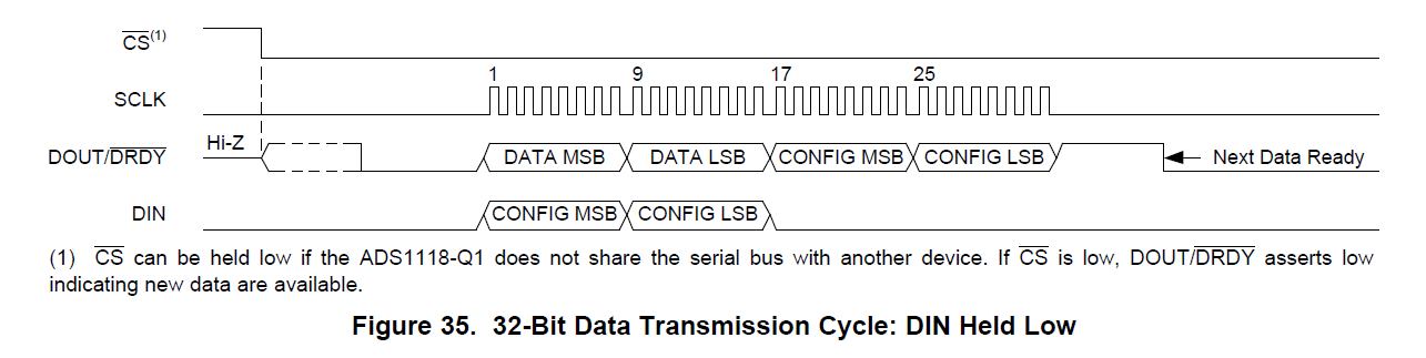
They using continue mode, and each channel configure as 0x44E3/0x54E3/0x64E3.

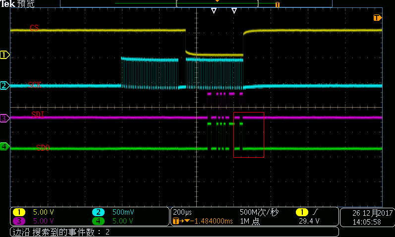
But when the system running at the temperature of 85C, some how it will read back a 0, while the normal read back data should be 200, the result show as below, they encountered 4 times the read back data is 0.

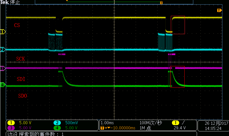
Besides, they found that, the SDO of ADS1118-Q1 will sometimes drop slow, which may cause incorrect conversion result.

Could you please help to check these high temperature wrong read back data issue and the SDO issue?

  • Fery,

    SDO drops low because /CS has been returned high. I've drawn another box around the /CS returned high in the picture. Just as /CS has returned high, the SDO line becomes Hi-Z and this causes the line to slowly drop to ground.

    One other thing that I noticed is that the SDI line continues to stay high well after the SCLK has finished. I don't think this is a problem, but I wanted to make sure your customer isn't trying to write to the device at that time.

    In the second plot, the SDO line was low, because the LSB read out ended with a 0. Here, the line had already dropped to ground.

    As for the error in the readout where the ADC reports 0 (or near 0) for output reading instead of 200, I can think of a couple of problems. First, I would verify that the /CS is returning low fast enough. In both plots, it looks like /CS start to go low fast, but then there is a slower time constant settling to get /CS to ground. I would make sure that /CS gets to ground before SCLK is clocked in. The customer can either add a pulldown resistor to /CS or add a delay before SCLK starts to clock. Second, I would check the timing diagram to see if there are any problems. The timing and switching diagrams are on page 8 of the datasheet.

    One other thing to check would be the configuration register with the read. In the scope shots you've provided, the customer already sends 32 bits for the read. This should send back the data and the configuration register. When the customer gets the error for a 0 read, what is the configuration register value with that read? It might show if the first SCLKs are missed because /CS is still high.

    Is the second scope shot a view of the error? It looks like the DIN and DOUT are exactly the same. Also, what should the write to the configuration register be? Here is a closeup of the plot:

    It looks like the DIN and DOUT both read 000Ch 54E6h. I don't think this is correct. The configuration register is written with the first byte of the readback. See Figures 40 and 41 of the datasheet. Also, I can't really see the actual timing, but check to see that there is enough time for SCLK low.

    Send my comments back to the customer and let me know if they have questions.

    Joseph Wu

  • Fery,

    I'm sorry but I meant to show a different plot for /CS returning high and SDO slowly drifting low. This shows that SDO goes Hi-Z when /CS returns high. It's now fixed in my first plot, but here it is again, just in case you didn't see it in the post.

    Joseph Wu

  • Fery,


    I haven't heard from you for a while and I thought I'd check to see if the customer was able to solve the problem with bad data.

    In my last posts I'd mentioned that the timing for /CS going high will make the DOUT go high-z, which made the DOUT slowly go low. However, I'm not sure that would cause the problems that your customer is seeing. In the plot of the data, it looks like the data comes out as 0V for the error.

    If your customer has solved the problem, I'd like to close out this post. However, if your customer has not solved the problem, read through my comments in the previous posts and get back to me with more information.


    Joseph Wu
  • Hi Joseph,

    For above screenshot, the channel 3(SDI) and channel 4 (SDO) are both connect to SDO, so they are showing the same waveform.

    Please check below corrected screenshot for /CS/CLK/SDI/SDO. The timing should be satisfied the SPI requirement.

    Customer feedback that readout data incorrect problem just happen at high temperature under 85 degree centigrade, for lower temperature, which as low as -40 degree, they haven't encountered same issue. So could you help to check whether high temp. will cause this issue?

    Besides, customer is running at continue conversion mode, and monitor 6 different channel with 2 pcs ADS1118-Q1, so they are switching the MUX setting to monitor different channel, each channel configure as 0x44E3/0x54E3/0x64E3.

    And I wondering, if I write the register as 0x44E3 in last cycle, the read back data is for AIN0 channel or AIN1 channel in the most recent cycle? And what is the data stored in the register after switching the channel? 

  • The corrected screenshot for /CS/CLK/SDI/SDO should show as below.

  • Fery,


    We've been talking about your application and we might have a thought about what is happening. First, I would change the mode of operation from continuous conversion mode to single shot conversion mode. I think this will make the problem disappear.

    We think that there may be a problem in the timing, where the device is being read out and just as a new conversion is starting. As the conversion completes, the data is read out. At the next read, the data has been read out and may give an error read of 0 because the data has already been read.

    This may have some temperature dependence if the internal oscillator gets faster with temperature. This may explain why the problem occurs at 85C, but not at normal temperature.

    If single shot conversion is used, then the start of the conversion is known, so that the read can be timed based on the data rate and any change in the oscillator frequency. If the data rate used is 860SPS, the nominal data period is 1.16ms. Using single shot conversion, start the conversion, and then wait 20us for the device to start up. The wait the data period + 10% for oscilator variability.

    Total, this would be a start single conversion, then wait about 1.3ms to read out the data. Using single-shot conversion mode, I think this read error would disappear.


    Joseph Wu
  • Hi Joseph,

    You mean that, at continue mode, if the conversion completes and I read out the data, then the register value will become 0 before next conversion complete?

    But customer read out the conversion data every 2.5ms, and the read process will complete within ~400us, so I think there is enough time to complete the conversion with 860SPS before next read cycle, right?

    And for the single shot conversion, the total time needed for one read cycle is about 1.3ms right?

  • Fery,

    A timing problem might come in for the data is being latched to the DOUT/DRDY. If the data read and the latching occur at the same time.

    One other thing that could work would be to keep the device in continuous conversion mode, but change the read timing. Each time the /CS is set low the master should wait for the conversion to complete. This would require the master to read on the transition of DOUT/DRDY going low (not when it is low, but have the read edge triggered). The master would need to find the /DRDY pulse shown in Figure 38. Then the device can be read.  Figure 38 is shown below:

    In the end, using single-shot mode would be a much simpler mode of operation.

    Joseph Wu

  • Fery,


    Was your customer able to test the device in single-shot mode? I think using single-shot conversion mode will clear up the problem of a bad read. When the read is interrupted by a new data, there may be problems in the resulting data.

    I'll close this post for now, but if you need further assistance with this question, you should be able to post back to this thread for more questions.


    Joseph Wu