This thread has been locked.

If you have a related question, please click the "Ask a related question" button in the top right corner. The newly created question will be automatically linked to this question.

ADS1298: Noise, spikes in acquired ADC data

Part Number: ADS1298

Hi, thank you for reading my post.

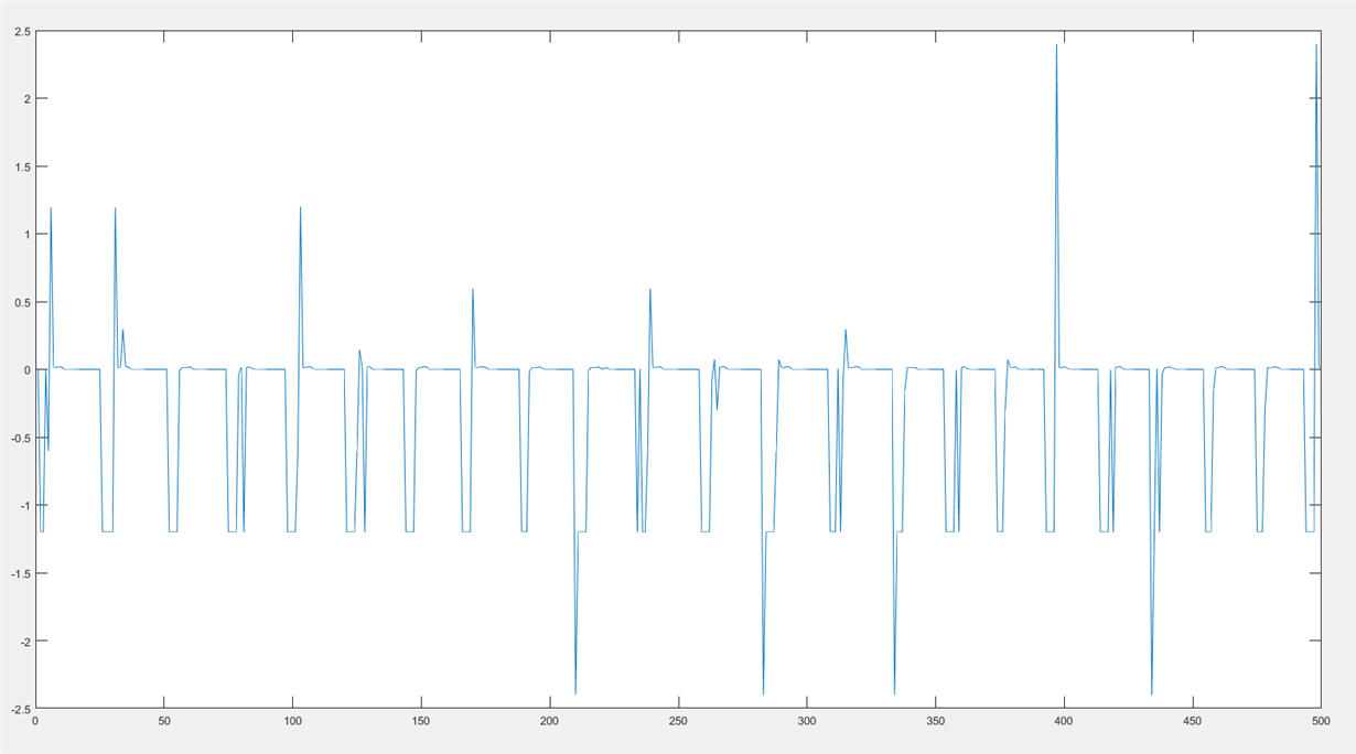
My team is building a 16-channel EMG acquisition device by using two ads1298. We use bipolar +-2.5V power supply, internal reference of 2.4V and internal oscillator. For each channel, before the signal going into the adc input, the signal will go through a instrumental amplifier, a high pass filter with about 15Hz cutoff, and a low pass filter for anti-aliasing. We followed the power-up sequence for the adcs. The setup of the adc seems fine. we were able to set and read back all registers. However, the adc data acquired include some noise and spikes that we did not see (using oscilloscope) on the channel input pins. Since we use single ended configuration, all negative inputs are tied to the ground. Following are some data sample we acquired from the adc and plotted with MatLab. Each plot contain 500 samples, the y-axis is voltage.

 1. Tested with ADS1298 ECGFE eval board. We disconnected the DSP and the ADS1298 on the eval board, but keeping the power supply connection to supply power to the ADS1298. Then we connected the ADS1298 to our PIC microprocessor. The following data were acquired on the channel that is set to normal operation, gain of 1, normal electrode input. Note that there was nothing connected to the channel input. We expected to get 0V for all samples, but we saw these periodic spikes.

2. The setting is pretty much the same. The samples were also obtained from the testing with eval board. The only difference is that the channel is set to power-down, gain of 1, input-shorted.

3. We also have a ads1298 soldered on a breakout board and implemented on a bread board. Following is the data acquired with 500Hz, 2Vpk-pk sine wave input. The setting is 8kSPS, and gain of 1.

4. Same setup in 3, but with both positive input and negative input shorted to ground

We also ran similar tests on the PCB board we designed with two ads1298 and a PIC microcontroller. The acquired data had similar spikes in example 1 and 2.

We tested the communication between the microcontroller and MatLab. There is no problem in transmitting the data over USB port. We were also able to verify the status byte for each sample.

Does anyone know the possible causes of this issue and how to fix it? Thanks in advance.

  • Hi Xinyuan,

    Just curious, but how does your sine wave look when using the ADS1298ECGFE-PDK in it's original configuration? I suspect you are getting some corrupted data through the SPI interface on your controller. If you can provide some screen shots of the communication (SCLK, SDI/SDO, DRDY, etc) that would be helpful.
  • Hi Tom,

    When using the eval board with its original configuration, the sine wave looks fine.

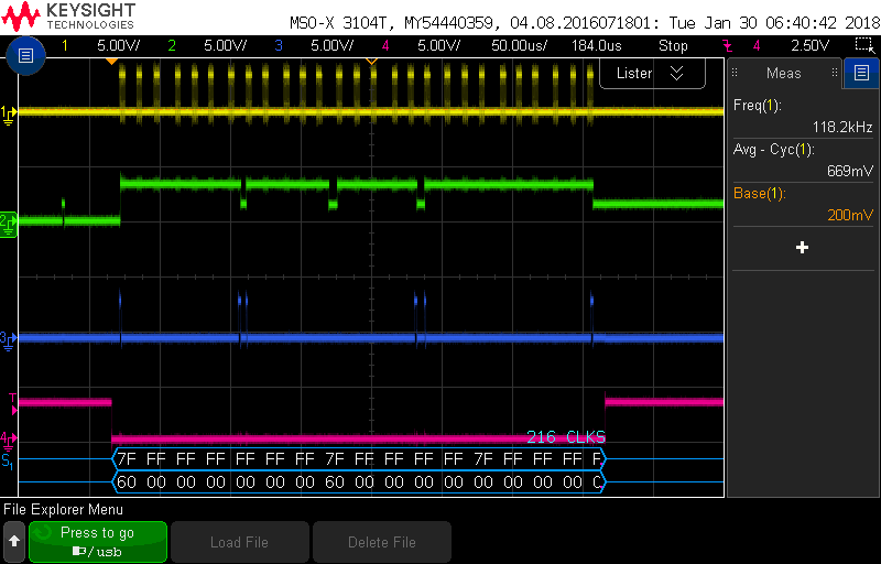
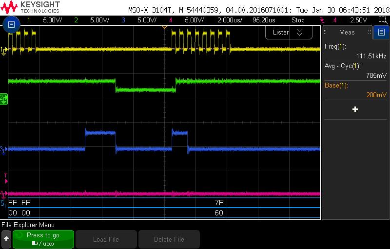
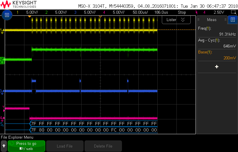
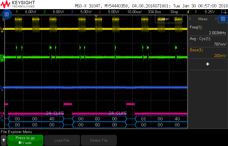
    Here are some SPI communication screen shots. The adc is set to HR mode, continuous mode, 8kSPS, 4MHz for SCLK. All channels are set to powered down. input shorted. Yellow signal is SCLK, green signal is DRDY, blue signal is data out from adc, pink signal is CS.

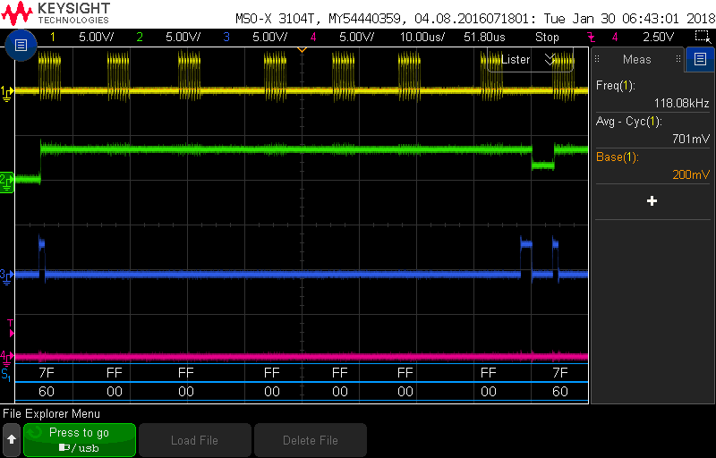
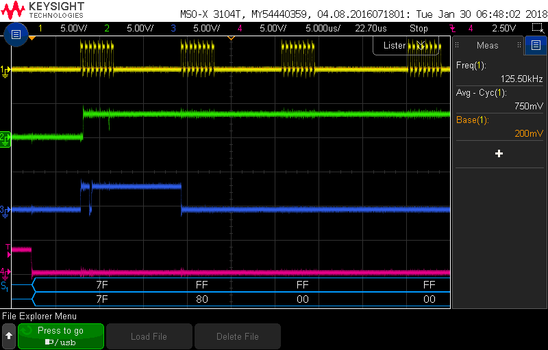
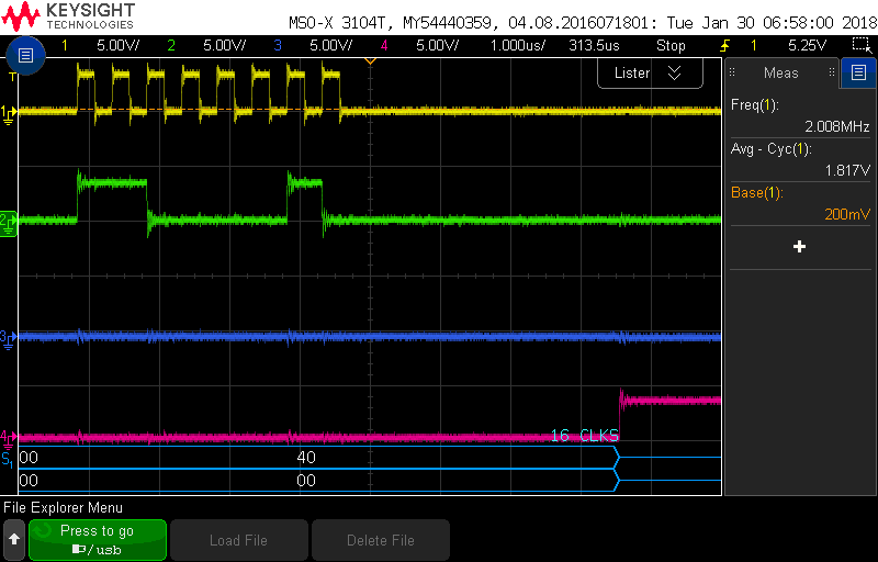
    We thought 4MHz SCLK might be too fast, even though the datasheet says it is the max acceptable SCLK frequency. We changed SCLK to 2MHz. The signal pike problem is still there. Following are some communication screen shot with 2MHz SCLK

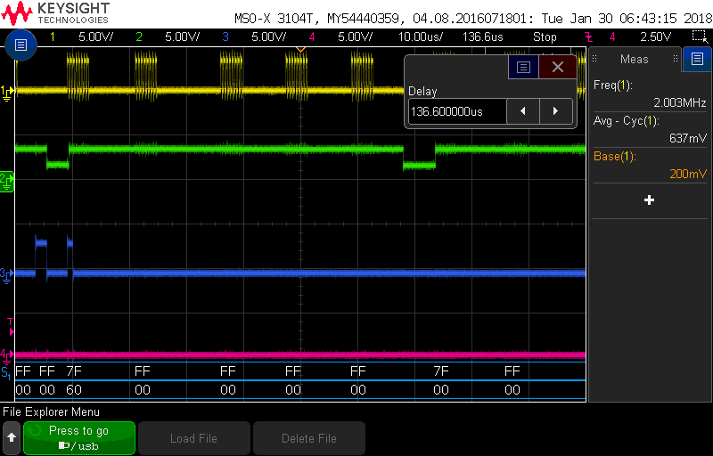
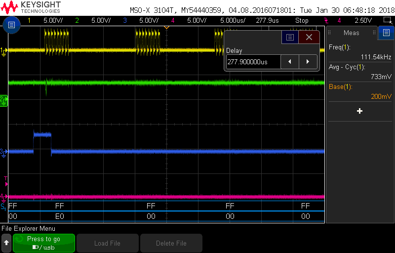
    We also too some screen shot during command sending. Now green signal is adc data in.

    During the test with digital analyser, the spike pattern become more like the one in picture number 4 (with slightly fewer spikes), instead of the one in picture number 1 and 2 in the main post. I am not sure what to look for in these spi communication screen shot, since I can not predict what value the adc may send out during conversion. I was able to send commands and read register values successfully. If the SPI communication is corrupted, shouldn't I see in correct values when I try to read back register values? Or may be it is the synchronizing issue between DRDY and data reading?

    I use DRDY as an external interrupt trigger in the microcontroller. When it goes low, the interrupt will fire. The while loop that pulling the flag set by the interrupt will end and proceed to data reading. After completing data reading, the flag is reset. The cycle starts again.

    It would be great if you can help to identify the issue. Thank you so much. 

  • Hi Xinyuan,

    Are these screen shots from your hardware? One thing to note is the level of the DRDY signal - it should transition to a logic '0' while in these captures it seems to be about mid-scale voltage. That indicates there may be some sort of 'bus contention' associated with that signal. Make sure the controller pin connected to DRDY is set as an input. The other thing is that DRDY should be consistent, going active at the data rate set up in the configuration registers. In the first screen shot above, you can see there are time differences between the application of the DRDY pulse. Try speeding up the SCLK and slowing down the data rate of the ADS1298. You can also try repeating the above captures on the original hardware to see what the communication should look like. Rather than applying a sine wave input, you could just apply a DC signal which would give you a consistent data output (with some LSBs toggling perhaps), that would help you in your debug process.
  • The screen shot posted are from the PCB my team designed, which uses two ADS1298

    For the DRDY bus contention issue, I found out that the DRDY pins from both ADS1298s are connected together. We disconnected one of them from the microcontroller. logic "0" on DRDY pins is 0V now.

    I also found out that our microcontroller is not fast enough to pull out data with the DRDY toggle frequency, when the data rate is too high. That's why the timing of DRDY on the screen shots are not consistent.

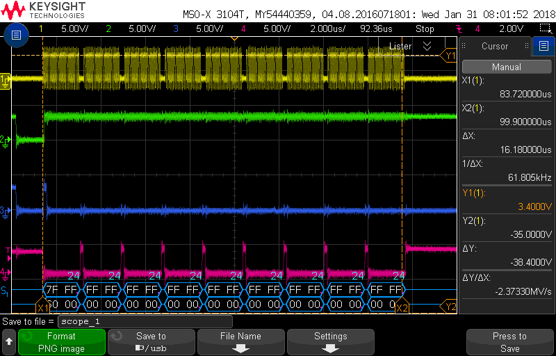
    Following is the SPI communication from the eval board. I notice that the SCLK is about 15MHz. The data reading mode is one-shot mode? Sine the CS pin is toggled for every channel data reading? Also is the data bus 24bits instead of normal SPI 8bits bus? Because every channel data reading has 24 continuous CLKs 

    I also notice that most of the spikes (almost all of them) in the data reading are exactly -1.2V, which is about half of the reference voltage 2.4V. It is also the same voltage on the VCAP1 pin with respect to AVSS, the negative power supply. Is possible that one of these voltages affects the signal?

    I will ran the analyser with a DC input and see if I can identify any issue.

    Thank you!!!

  • Hi Xinjuan,

    The DSP used on the MMB0 can do 24 bit SPI, so that's why you don't see 8-bit breaks. Have you resolved the issue now?