This thread has been locked.

If you have a related question, please click the "Ask a related question" button in the top right corner. The newly created question will be automatically linked to this question.

DAC8760: DAC8760 Output current is interfered by walkie-talkie

Part Number: DAC8760
Other Parts Discussed in Thread: TIPD153

Dear TI Support Team


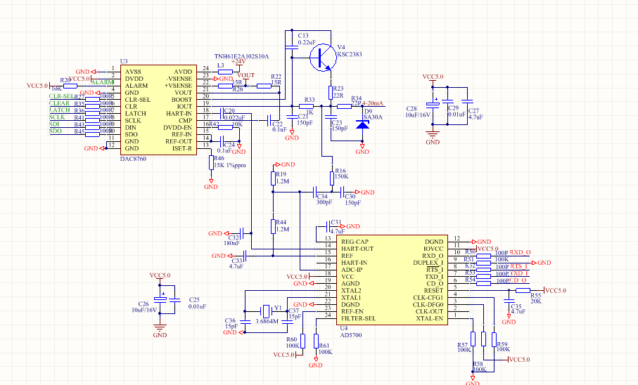
         We used DAC8760 to convert digital signal into current signal on the Combustible Gas Detector.We used the multimeter to measure the output current of DAC8760,the test value is normal.

But the application field require the product can be passed in the anti-interference test that make a working walkie-talkie close to the product,the test value of multimeter is 2mA above original value.

We think the 2mA error is caused by  walkie-talkie interference,but the RF frequency of walkie-talkie is above 100MHz and the sample rate of DAC8760 is 40KSPS(40KHz).

How can caused 2mA error on output current of DAC8760?

Thanks

  • Yulei,

    What is the DAC8760 hardware platform that this test is being conducted on? An EVM board? An EMC-EVM board? Custom hardware? If it's custom hardware, can you share the schematic? RF artifacts may not entirely be dependent on devices soldered to the board, but also the board itself if unintentional antennae have been created in the copper.

    The components in the DAC8760 output stage are definitely <1MHz BW, so it would be somewhat surprising for the device to respond to RF stimulation from the walkie talkie. In TIPD153 we conducted radiated immunity testing on the board pursuant to IEC61000-4-3 which swept from 80MHz to 1GHz at 20V/m - which is most likely stronger than the walkie talkie. In the case of the current output some disturbance was observed but nothing that caused the output to deviate by larger than 0.08% FSR (for the 0-24mA range, ~20uA).

    How are you measuring or observing the output disturbance? One potential difference between your setup and what was done in TIPD153 is that TIPD153 was measured using a 6.5 digit DMM in "fast 5.5 digit" mode - so there was some averaging etc. simulating something close to what would be expected of a PLC analog input module.

  • Yulei,

    Any update on this thread? If you were able to reach closure, could you please let us know the outcome?
  • Hi Kevin

         The DAC8760 hardware is Customer's PCB and the schematic is following:

    The PCB Layout is following:

    The working frequency of walkie talkie is 100~500MHz,we keep a distance of 1 centimeter between walkie talkie and DAC8760 PCB,and use the multimeter measure the average output current of DAC8760,so the test value is 2~3mA higher than when the walkie talkie far away from the PCB.

    We don't know how the walkie talkie disturb the DAC8760 by now?

  • Hi Yulei,

    I would suggest a couple more measurements are made so that we can better understand the situation. So far, we just know that there appears to be a 2-3mA offset observed on the IOUT terminal block.

    1. Using an oscilloscope, is IOUT stable without interference from the walkie talkie?
    2. Can we see an oscilloscope measurement of IOUT while exposed to the walkie talkie?
    3. Does the size of the offset caused by the walkie talkie change depending on the DAC code?
    4. Is any change in voltage observed at the node between ISET-R and R46?
    5. With IOUT disabled, is there an offset caused at the IOUT terminal by the walkie talkie?
    6. Is any change observed in the REF-OUT or REF-IN voltage during exposure to the walkie talkie interference?
    7. Is the voltage output impacted by the walkie talkie interference?
    8. Is AVDD impacted by the walkie talkie interference?
    9. Is the voltage at the HART-IN pin impacted by the walkie talkie interference?

  • Yulei,

    Any follow up on this thread? Do the suggested tests in my previous post make sense? Any questions?
  • Hi Kevin

    Thanks for your suggestion for this issue. The customer measured the ISET-R,REF-IN(or REF-OUT) and AVDD voltage compared with the walkie talkie close to the PCB when the input value of DAC is calibrated to zero point.
    Test result Without the walkie talkie:ISET-R:0V,REF-IN(or REF-OUT):5V,AVDD:28~29V,Output Current:4mA;
    Test result With the walkie talkie close to the PCB(4~20mA Output Cable):ISET-R:300~400mV,REF-IN(or REF-OUT):5.4~5.5V,AVDD:29~30V;Output Current:4.3~4.6mA;
    We found the internal reference was out of Spec(4.995~5.005V)and it may be the root cause to the offset on output current.
    so we want to try the high-accuracy external reference instead of internal reference,which part number do you suggest?
    What is your opinion for the reason that the internal reference is interfered by walkie-talkie?

    Thanks
  • Yulei,

    I think trying an external reference source is an excellent experiment to try given the observations you have provided. A 500mV shift in the reference voltage is unexpected - was this measurement made with a digital multi-meter or with an oscilloscope? I would be interested to know whether there is a true DC shift in the value or if an AC artifact is coupled to the reference voltage creating the illusion of a DC-shift when measured with the meter. Also, does the measured reference value return to normal when the Walkie-Talkie is removed?

    I do find it interesting that the supply voltage also appears to have been affected by the Walkie-Talkie since that voltage increased by ~1V.

    In this test setup is the external RSET being used? I'm trying to make sense of the measurements provided at the ISET-R pin.

    For an external reference source I would first suggest that you try something simple - just use some bench-top equipment to provide a voltage here. It doesn't need to be precise since all we're really interested in seeing at this stage is if the IOUT shift is purely related to what is happening with the DAC8760 internal reference or if there's additional effects in the signal chain. If we don't see a shift between cases with and without the walkie talkie then we know that an external reference is a viable option to correct this behavior in the design.

    For selecting an external reference solution I would need to know more about the accuracy goals of this design in order to steer that decision.
  • Hi Yulei,

    Any updates? Have they conducted the tests with the external reference?

    Also inserting the questions from my last post once more below:

    Duke of DACs said:
    A 500mV shift in the reference voltage is unexpected - was this measurement made with a digital multi-meter or with an oscilloscope?

    Duke of DACs said:
    Does the measured reference value return to normal when the Walkie-Talkie is removed?

    Duke of DACs said:
    In this test setup is the external RSET being used?

  • Hi Yulei,

    Checking in once more for an update on this topic...