This thread has been locked.

If you have a related question, please click the "Ask a related question" button in the top right corner. The newly created question will be automatically linked to this question.

ADS1115: Recommended current limit for ESD diodes forward-conducting from GND to AIN?

Part Number: ADS1115


Hello,

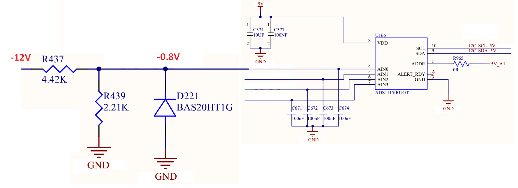
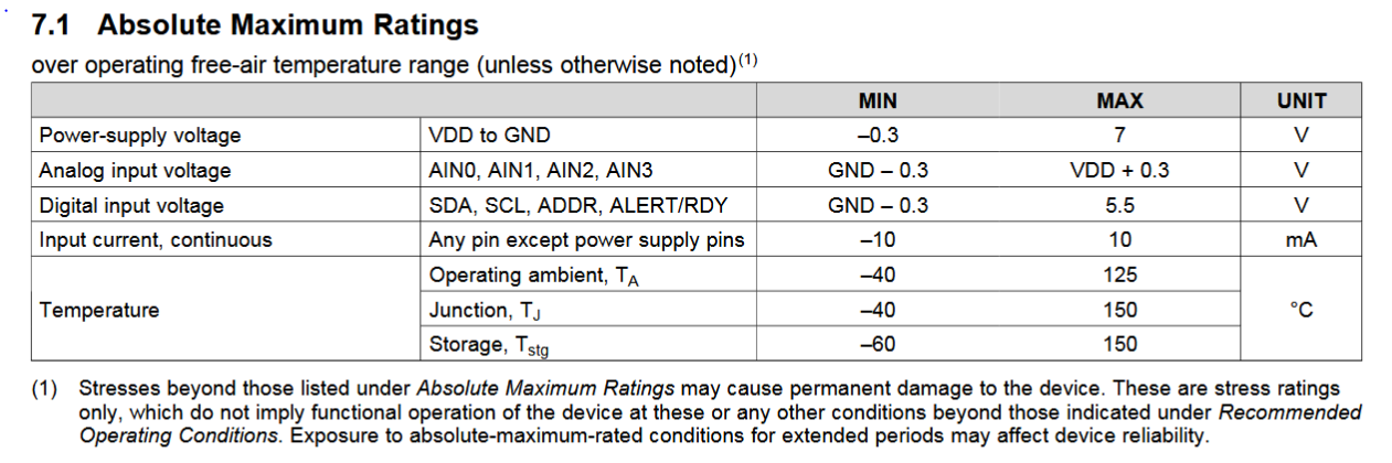
On our application specific board analog inputs are fed to the board via cables. They go through LT6375 Common Mode Voltage Difference Amplifier and then fed to ADS1115 inputs. LT6375 is powered with +12V and -12V. If for some reason one of the inputs of LT6375 is open or short to GND (cables broken) the output of LT6375 may be negative rail ie. -12V, Which is then fed to ADS1115 input pin through a series resistor and one paralel protection diode. (Schematic attached) 

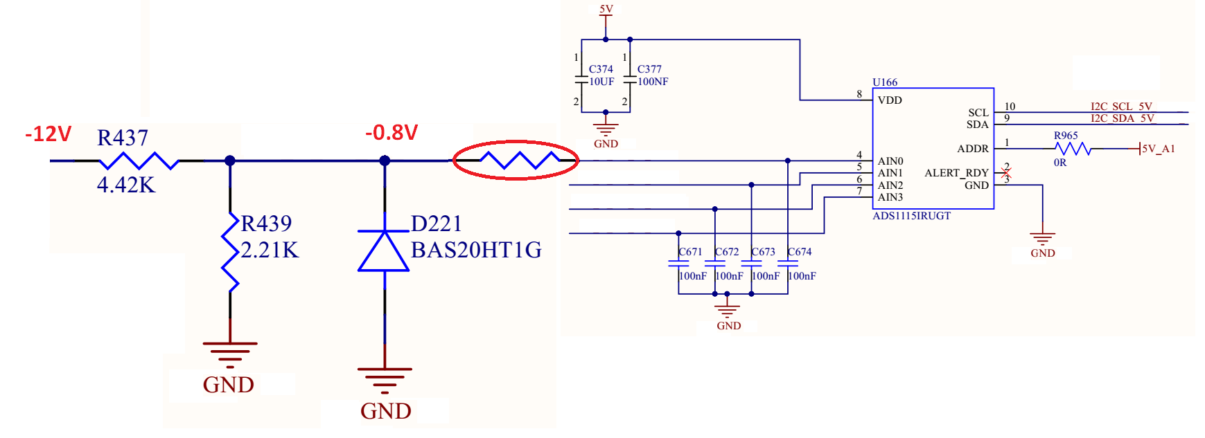
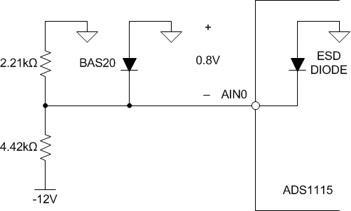
Will ADS1115 ESD protection diodes be able to withstand 3mA of continues current from GND to AIN through the ESD protection diodes?

Also if for some reason the ESD protection diode is damaged, will that only effect that specific input channel or will all of ADS1115 input channels be unusable?

Thanks for your help,

Sahi

  • Sahi,

    The ADS1115 datasheet gives an absolute maximum ratings table on page 6 of the datasheet. This states that for any analog input pin, the voltage must be within GND-0.3V and VDD+0.3V. Also, the maximum input current is ±10mA.

    However, your schematic shows that you may violate both conditions. First, D221 holds AIN0 at -0.8V when the -12V appears on the front end. This violates the input voltage maximum. Second, when D221 gets pulled down to -0.8V, current flows from GND into the AIN0 of the device. I'm not sure what that current is, but it is certainly possible that this is more than 10mA. The current is not limited by just the current in R437 or R439.

    In order to protect the device, I would recommend a series resistance to AIN0 like this:

    This should limit the input current going into the device, to 0.8V / R. I would imagine that a 1kΩ resistor should be sufficient.

    Joseph Wu

  • Hi Joseph,

    Thank your for the reply. Just a couple of questions.

    When D221 gets pulled down to -0.8V, current flows from GND into the AIN0 of the device. But I think that current must pass through R437. It can not pass through D221 as current can not flow from GND to GND. So the current may be roughly 3mA maximum. It will probably be less. Am I missing something?

    If this assumption is correct will ADS1115 ESD protection diodes be able to stand 3mA continous current?

    And if for some reason AIN0 ESD didoes are damaged, will we still be able to use other channels of the same ADS1115 device?

    Thanks.

    Sahi 

  • Sahi,

    Yes, you're correct, the current will be limited by the series resistance if the 4.42kΩ resistor. I was thrown by having 0.8V across the diode. I've redrawn the schematic so it's easier for others to follow.

    In that case the ESD diode should be able to take the 3mA of current because the maximum current is ±10mA. However, that doesn't protect you from keeping AIN0 within 0.3V below GND. To do that you still require a series resistance. If you exceed the voltage of 0.3V below GND, there may be damage to the device. This damage is not necessarily limited to the ESD diode and not just to the individual channel that experienced the over voltage condition.

    If you insert the series resistance you should be able to protect the device and inputs.

    Joseph Wu