Because of the holidays, TI E2E™ design support forum responses will be delayed from Dec. 25 through Jan. 2. Thank you for your patience.

This thread has been locked.

If you have a related question, please click the "Ask a related question" button in the top right corner. The newly created question will be automatically linked to this question.

ADC128D818: More difficulty reading and interpreting the 16-bit channel registers

Part Number: ADC128D818

While I can perform full reading/writing of the 8-bit registers, I'm having trouble with the 16-bit channel regs. I have verified my ability to read/write by reading Manufacturer ID Register 0x3E as 1 and revision as 9 and I can also write values to the Interrupt Mask Register and read them back so I think there's nothing wrong with my hardware or basic understanding.

However, as per Figure 31, the 16-bit channel value readings make no sense to me. As a basic test, I expect to read temperature in channel 7 (using mode 0). The first issue is interpreting the format based on what I can understand from the datasheet. As well as reading the datasheet I have searched these forums but still have no definitive answer as to how the channel values are padded. Regardless, no interpretation I can guess at makes sense of the values I get.

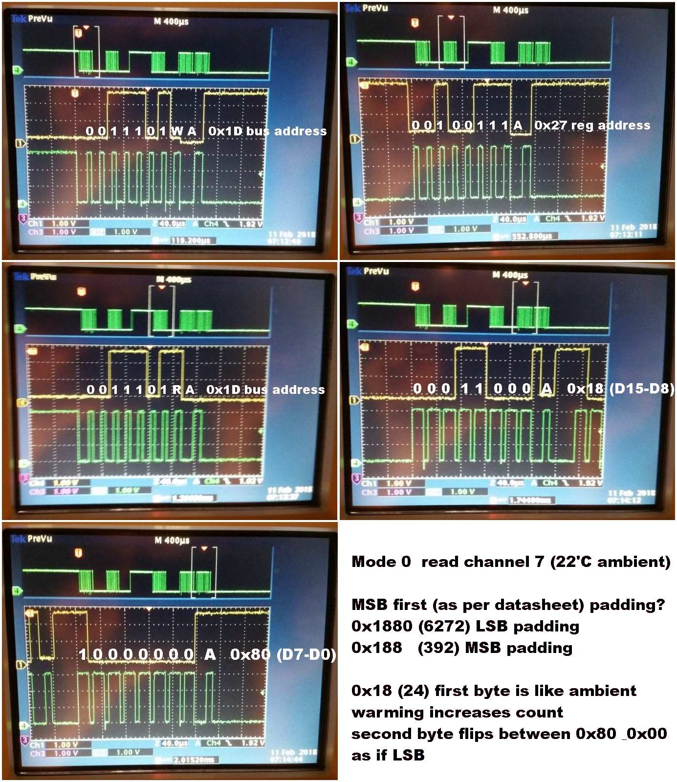
So, having initialised the IC into mode 0 (as per 9.2.2.2.1 Quick Start) I always get temperature readings in channel 7 that make no sense, although the values do increase/decrease as I gently warm/cool the part. I have analysed the I2C bus with a scope and placed a 100R between microcontroller and SDA (1K pull-ups on SDA & SCL on the slave side) which allows me to check whether it is the master or slave asserting the lows. Everything look OK to me and the data received and reported by the microcontroller agrees with what is shown on the scope. The following sequence of scope shots shows the problem:

(Note the assertion of SDA by the slave is visible as a 0.2V drop)

I understand the datasheet as saying the 16-bit vales are read back MSB first and padding is in the higher value bit positions (not explicitly stated though). The temperature is stated as being x 2 so I expect 22'C ambient to return 44. However I see nothing like this. I do notice that by ignoring the datasheet and treating the top-bit of the second byte as decimal 0.5 then the first byte does indeed make sense as temperature directly in degrees, with the fractional part split over in the LSB.  This would actually be a sensible encoding scheme.

Assuming I can resolve the above issue, my other question is whether it is legitimate to read all channels by presetting the first address and continually clocking out successive bytes as per the two-byte read as per "Figure 31" - i.e.  just keep clocking for as many pairs as required.

  • Hi Adrian,

    Welcome to our e2e Forum! The temperature read in the ADC128D818 is only 9-bits. So what I believe you are seeing is binary 000110001 (LSB's padded with zeros) but that would be 0x31 or decimal 49, which would be 24C. If you have an oven available, you could soak the board at a higher temp for a few minutes and see what values you get. I'm not sure about the second portion of your question - regarding reading all channels back to back. I suspect that won't give you the desired results, but I'll check and let you know what I find out.
  • Hi Tom, thanks for helping out. Indeed, as I experimented with before, treating the two-byte readout as a 9-bit value top-aligned with bit 15 (as identified in Figures 29 & 31) does agree fairly well with an external thermometer when I artificially heat and cool the IC (with bit 7 weighted as 0.5C)

    A succinct way of calculating the value would then be to floating-point divide the full 16-bit readout by 256. 

    However, nowhere can I see an explicit description of the data alignment and in a design review I'd rather like to be able to relate my implementation with the relevant information provided in the datasheet. If I've missed it somewhere I'd certainly appreciated a vector to it.

    -- As for the second part of my question, with a little further experimentation I found that sequentially reading channels without repeating the setting of the Channel Readings Register Addresses doesn't work as I'd hoped for. The datasheet hints to me that it might be possible when it talks of the " Preset Internal Address Register":

    Figure 26. Serial Bus Interface Write Example 1 - Internal Address Register Set Only

    Figure 28. Serial Bus Interface Read Example 1 - Single Byte Read With Preset Internal Address Register

    Figure 29. Serial Bus Interface Read Example 2 - Double Byte Read With Preset Internal Address Register

    But it just allows the same register to be read over and over again without addressing it each time. An auto-increment address register is unfortunately not a feature of this device which is rather a shame when multiple channels are in use.

    Thanks, I think we're all done now.