Other Parts Discussed in Thread: MSP430F5132
Tool/software: Code Composer Studio
Hello,
I couldnt make my ADS8684 work on my custom circuit.
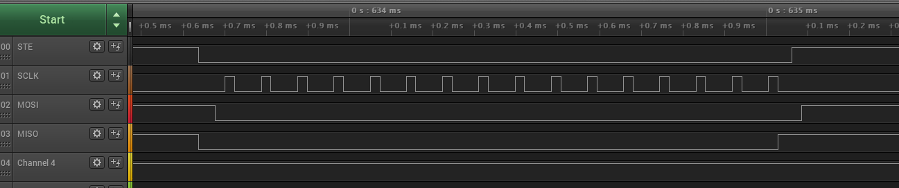
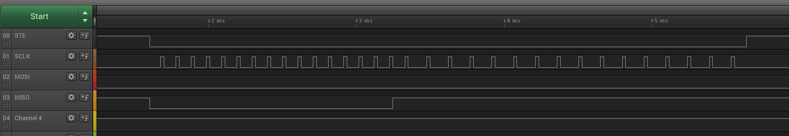
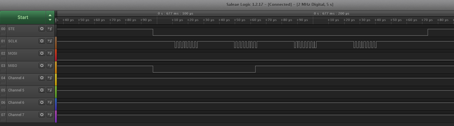
Here is the logic analyzer output:
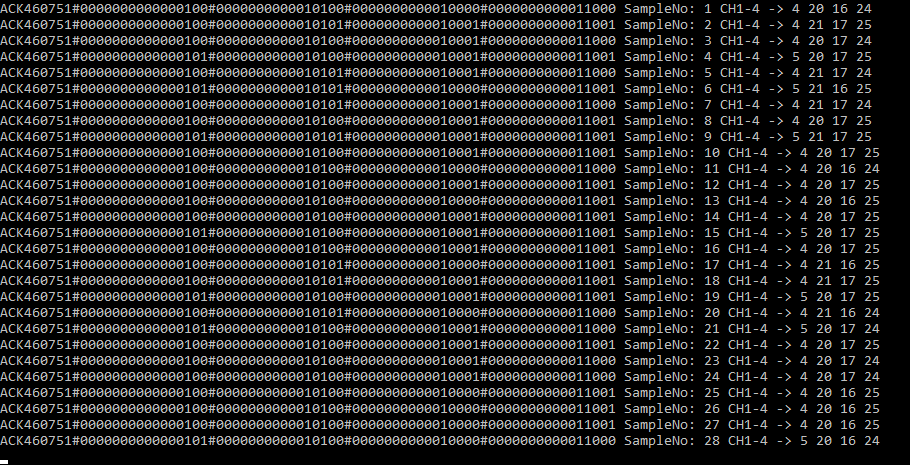
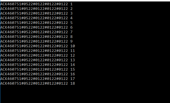
uart output:
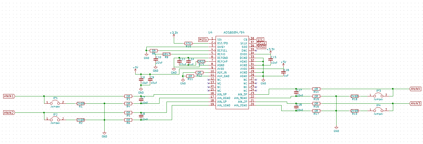
ADS8684 circuit:
MSP430F5132 codes:
>>>>>>>>>>>>>>>>>>>>>>>>>>>>>>main.c<<<<<<<<<<<<<<<<<<<<<<<<<<<<<<<<
#include <string.h>
#include <stdio.h>
#include <stdlib.h>
#include "driverlib.h"
#include "msp430_spi.h"
char charArray[20],charArrayID[6],cbuf1[1],cbuf2[1],cbuf3[1],cbuf4[1],cbuf5[1],cbuf6[1],cbuf7[1],cbuf8[1],cbuf9[1],cbuf10[1],cbuf11[1],cbuf12[1],cbuf13[1],cbuf14[1],cbuf15[1],cbuf16[1];
volatile int i,c=0;
uint8_t receivedData = 0x00,buf1,buf2,buf3,buf4,buf5,buf6,buf7,buf8,buf9,buf10,buf11,buf12,buf13,buf14,buf15,buf16;
//uint8_t buf[16];
void main (void)
{
//Stop WDT
WDT_A_hold(WDT_A_BASE);
//STATUS1 STATUS2 output
GPIO_setAsOutputPin(GPIO_PORT_P3,GPIO_PIN0 + GPIO_PIN1);
//STATUS1 STATUS2 low
GPIO_setOutputLowOnPin(GPIO_PORT_P3,GPIO_PIN0 + GPIO_PIN1);
//rs485 de re
GPIO_setAsOutputPin(GPIO_PORT_P2, GPIO_PIN0 + GPIO_PIN1);
//re de low
GPIO_setOutputLowOnPin(GPIO_PORT_P2, GPIO_PIN0 + GPIO_PIN1);
//uart - rs485
GPIO_setAsPeripheralModuleFunctionInputPin(GPIO_PORT_P1, GPIO_PIN1 + GPIO_PIN2);
//spi - ste = p1.0
spi_init();
GPIO_setAsOutputPin(GPIO_PORT_P1, GPIO_PIN0);// + GPIO_PIN3 + GPIO_PIN4 + GPIO_PIN5);
GPIO_setOutputLowOnPin(GPIO_PORT_P1, GPIO_PIN0);// + GPIO_PIN3 + GPIO_PIN4 + GPIO_PIN5);
//GPIO_setOutputHighOnPin(GPIO_PORT_P1, GPIO_PIN0);
//Baudrate = 9600, clock freq = 1.048MHz
//UCBRx = 109, UCBRFx = 0, UCBRSx = 2, UCOS16 = 0 --> Copied from MSP430F5529 example
USCI_A_UART_initParam param = {0};
param.selectClockSource = USCI_A_UART_CLOCKSOURCE_SMCLK;
param.clockPrescalar = 109;
param.firstModReg = 0;
param.secondModReg = 2;
param.parity = USCI_A_UART_NO_PARITY;
param.msborLsbFirst = USCI_A_UART_LSB_FIRST;
param.numberofStopBits = USCI_A_UART_ONE_STOP_BIT;
param.uartMode = USCI_A_UART_MODE;
param.overSampling = USCI_A_UART_LOW_FREQUENCY_BAUDRATE_GENERATION;
if(STATUS_FAIL == USCI_A_UART_init(USCI_A0_BASE, ¶m))
{
return;
}
//Enable UART module for operation
USCI_A_UART_enable(USCI_A0_BASE);
//Enable Receive Interrupt
USCI_A_UART_clearInterrupt(USCI_A0_BASE,USCI_A_UART_RECEIVE_INTERRUPT);
USCI_A_UART_enableInterrupt(USCI_A0_BASE,USCI_A_UART_RECEIVE_INTERRUPT);
//CIHAZ ID
charArrayID[0] = '4';
charArrayID[1] = '6';
charArrayID[2] = '0';
charArrayID[3] = '7';
charArrayID[4] = '5';
charArrayID[5] = '1';
//ads8684 ayarlar
///reset
GPIO_setOutputLowOnPin(GPIO_PORT_P1, GPIO_PIN0);
//__delay_cycles(1000);
spi_transfer16(0x8500);
GPIO_setOutputHighOnPin(GPIO_PORT_P1, GPIO_PIN0);
__delay_cycles(1000);
//AUTO_SEQ_EN
GPIO_setOutputLowOnPin(GPIO_PORT_P1, GPIO_PIN0);
__delay_cycles(1000);
spi_transfer16(0x01FF);
GPIO_setOutputHighOnPin(GPIO_PORT_P1, GPIO_PIN0);
__delay_cycles(1000);
//CHANNEL POWER DOWN -> ALL UP
/*GPIO_setOutputLowOnPin(GPIO_PORT_P1, GPIO_PIN0);
__delay_cycles(1000);
spi_transfer16(0x0200);
GPIO_setOutputHighOnPin(GPIO_PORT_P1, GPIO_PIN0);
__delay_cycles(1000);*/
//channel 1 2.5xVref
GPIO_setOutputLowOnPin(GPIO_PORT_P1, GPIO_PIN0);
//__delay_cycles(1000);
spi_transfer16(0x0505);
GPIO_setOutputHighOnPin(GPIO_PORT_P1, GPIO_PIN0);
__delay_cycles(1000);
//channel 2 2.5xVref
GPIO_setOutputLowOnPin(GPIO_PORT_P1, GPIO_PIN0);
//__delay_cycles(1000);
spi_transfer16(0x0605);
GPIO_setOutputHighOnPin(GPIO_PORT_P1, GPIO_PIN0);
__delay_cycles(1000);
//channel 3 2.5xVref
GPIO_setOutputLowOnPin(GPIO_PORT_P1, GPIO_PIN0);
//__delay_cycles(1000);
spi_transfer16(0x0705);
GPIO_setOutputHighOnPin(GPIO_PORT_P1, GPIO_PIN0);
__delay_cycles(1000);
//channel 4 2.5xVref
GPIO_setOutputLowOnPin(GPIO_PORT_P1, GPIO_PIN0);
//__delay_cycles(1000);
spi_transfer16(0x0805);
GPIO_setOutputHighOnPin(GPIO_PORT_P1, GPIO_PIN0);
__delay_cycles(1000);
GPIO_setOutputLowOnPin(GPIO_PORT_P1, GPIO_PIN0);
//__delay_cycles(1000);
spi_transfer16(0xA000);
spi_transfer16(0x0000);
GPIO_setOutputHighOnPin(GPIO_PORT_P1, GPIO_PIN0);
__delay_cycles(1000);
__enable_interrupt();
while(1){
GPIO_setOutputLowOnPin(GPIO_PORT_P3, GPIO_PIN0);
GPIO_setOutputHighOnPin(GPIO_PORT_P3, GPIO_PIN1);
__delay_cycles(105000);
GPIO_setOutputLowOnPin(GPIO_PORT_P3, GPIO_PIN1);
GPIO_setOutputHighOnPin(GPIO_PORT_P3, GPIO_PIN0);
__delay_cycles(105000);
__disable_interrupt();
//CH1
GPIO_setOutputLowOnPin(GPIO_PORT_P1, GPIO_PIN0);
//__delay_cycles(10000);
buf1 = spi_transfer(0x00);
buf2 = spi_transfer(0x00);
buf3 = spi_transfer(0x00);
buf4 = spi_transfer(0x00);
GPIO_setOutputHighOnPin(GPIO_PORT_P1, GPIO_PIN0);
__delay_cycles(10000);
//CH2
GPIO_setOutputLowOnPin(GPIO_PORT_P1, GPIO_PIN0);
//__delay_cycles(10000);
buf5 = spi_transfer(0x00);
buf6 = spi_transfer(0x00);
buf7 = spi_transfer(0x00);
buf8 = spi_transfer(0x00);
GPIO_setOutputHighOnPin(GPIO_PORT_P1, GPIO_PIN0);
__delay_cycles(10000);
//CH3
GPIO_setOutputLowOnPin(GPIO_PORT_P1, GPIO_PIN0);
//__delay_cycles(10000);
buf9 = spi_transfer(0x00);
buf10 = spi_transfer(0x00);
buf11 = spi_transfer(0x00);
buf12 = spi_transfer(0x00);
GPIO_setOutputHighOnPin(GPIO_PORT_P1, GPIO_PIN0);
__delay_cycles(10000);
//CH4
GPIO_setOutputLowOnPin(GPIO_PORT_P1, GPIO_PIN0);
//__delay_cycles(10000);
buf13 = spi_transfer(0x00);
buf14 = spi_transfer(0x00);
buf15 = spi_transfer(0x00);
buf16 = spi_transfer(0x00);
GPIO_setOutputHighOnPin(GPIO_PORT_P1, GPIO_PIN0);
__delay_cycles(10000);
ltoa(buf1, cbuf1);
ltoa(buf2, cbuf2);
ltoa(buf3, cbuf3);
ltoa(buf4, cbuf4);
ltoa(buf5, cbuf5);
ltoa(buf6, cbuf6);
ltoa(buf7, cbuf7);
ltoa(buf8, cbuf8);
ltoa(buf9, cbuf9);
ltoa(buf10, cbuf10);
ltoa(buf11, cbuf11);
ltoa(buf12, cbuf12);
ltoa(buf13, cbuf13);
ltoa(buf14, cbuf14);
ltoa(buf15, cbuf15);
ltoa(buf16, cbuf16);
buf1 = 0;
buf2 = 0;
buf3 = 0;
buf4 = 0;
buf5 = 0;
buf6 = 0;
buf7 = 0;
buf8 = 0;
buf9 = 0;
buf10 = 0;
buf11 = 0;
buf12 = 0;
buf13 = 0;
buf14 = 0;
buf15 = 0;
buf16 = 0;
GPIO_setOutputHighOnPin(GPIO_PORT_P2, GPIO_PIN0 + GPIO_PIN1);
__delay_cycles(18000);
USCI_A_UART_transmitData(USCI_A0_BASE, 'A');
USCI_A_UART_transmitData(USCI_A0_BASE, 'C');
USCI_A_UART_transmitData(USCI_A0_BASE, 'K');
USCI_A_UART_transmitData(USCI_A0_BASE, charArrayID[0]);
USCI_A_UART_transmitData(USCI_A0_BASE, charArrayID[1]);
USCI_A_UART_transmitData(USCI_A0_BASE, charArrayID[2]);
USCI_A_UART_transmitData(USCI_A0_BASE, charArrayID[3]);
USCI_A_UART_transmitData(USCI_A0_BASE, charArrayID[4]);
USCI_A_UART_transmitData(USCI_A0_BASE, charArrayID[5]);
USCI_A_UART_transmitData(USCI_A0_BASE, '#');
USCI_A_UART_transmitData(USCI_A0_BASE, cbuf1[0]);
USCI_A_UART_transmitData(USCI_A0_BASE, cbuf2[0]);
USCI_A_UART_transmitData(USCI_A0_BASE, cbuf3[0]);
USCI_A_UART_transmitData(USCI_A0_BASE, cbuf4[0]);
USCI_A_UART_transmitData(USCI_A0_BASE, '#');
USCI_A_UART_transmitData(USCI_A0_BASE, cbuf5[0]);
USCI_A_UART_transmitData(USCI_A0_BASE, cbuf6[0]);
USCI_A_UART_transmitData(USCI_A0_BASE, cbuf7[0]);
USCI_A_UART_transmitData(USCI_A0_BASE, cbuf8[0]);
USCI_A_UART_transmitData(USCI_A0_BASE, '#');
USCI_A_UART_transmitData(USCI_A0_BASE, cbuf9[0]);
USCI_A_UART_transmitData(USCI_A0_BASE, cbuf10[0]);
USCI_A_UART_transmitData(USCI_A0_BASE, cbuf11[0]);
USCI_A_UART_transmitData(USCI_A0_BASE, cbuf12[0]);
USCI_A_UART_transmitData(USCI_A0_BASE, '#');
USCI_A_UART_transmitData(USCI_A0_BASE, cbuf13[0]);
USCI_A_UART_transmitData(USCI_A0_BASE, cbuf14[0]);
USCI_A_UART_transmitData(USCI_A0_BASE, cbuf15[0]);
USCI_A_UART_transmitData(USCI_A0_BASE, cbuf16[0]);
USCI_A_UART_transmitData(USCI_A0_BASE, '\n');
__delay_cycles(18000);
GPIO_setOutputLowOnPin(GPIO_PORT_P2, GPIO_PIN0 + GPIO_PIN1);
__enable_interrupt();
}
}
//******************************************************************************
//
//This is the USCI_A0 interrupt vector service routine.
//
//******************************************************************************
#if defined(__TI_COMPILER_VERSION__) || defined(__IAR_SYSTEMS_ICC__)
#pragma vector=USCI_A0_VECTOR
__interrupt
#elif defined(__GNUC__)
__attribute__((interrupt(USCI_A0_VECTOR)))
#endif
void USCI_A0_ISR(void)
{
switch(__even_in_range(UCA0IV,4))
{
//Vector 2 - RXIFG
case 2:
receivedData = USCI_A_UART_receiveData(USCI_A0_BASE);
/*if(receivedData != '#') // Check value
{
if((c == 0 && receivedData == '4') || (c == 1 && receivedData == '6') || (c == 2 && receivedData == '0') || (c >= 3 && c < 13) )
{
charArray[c] = receivedData;
c++;
charReceived = 0;
}else
{
c = 0;
charReceived = 0;
}
}else{
//c = 0;
//GPIO_toggleOutputOnPin(GPIO_PORT_P7, GPIO_PIN1);
charReceived = 1;
}*/
break;
default: break;
}
}
>>>>>>>>>>>>>>>>>>>>>>>>>>>>>>msp430_spi.c<<<<<<<<<<<<<<<<<<<<<<<<<<<<
#if defined(__MSP430_HAS_USCI_B0__) && defined(SPI_DRIVER_USCI_B)
void spi_init()
{
    /* Configure ports on MSP430 device for USCI_B */
    #ifdef __MSP430F5172
    P1SEL |= BIT3 | BIT4 | BIT5;
    #endif
    #ifdef __MSP430F5529
    P3SEL |= BIT0 | BIT1 | BIT2;
    #endif
    #ifdef __MSP430F5132
    P1SEL |= BIT3 | BIT4 | BIT5;
    #endif

    /* USCI-B specific SPI setup */

    UCB0CTL1 |= UCSWRST;
    UCB0CTL0 = UCCKPH | UCMSB | UCMST | UCMODE_0 | UCSYNC;  // SPI mode 0, master
    UCB0BR0 = 0x01;  // SPI clocked at same speed as SMCLK
    UCB0BR1 = 0x00;
    UCB0CTL1 = UCSSEL_2;  // Clock = SMCLK, clear UCSWRST and enables USCI_B module.


}

uint8_t spi_transfer(uint8_t inb)
{
    UCB0TXBUF = inb;
    while ( !(UCB0IFG & UCRXIFG) )  // Wait for RXIFG indicating remote byte received via SOMI
        ;
    return UCB0RXBUF;
}

uint16_t spi_transfer16(uint16_t inw)
{
    uint16_t retw;
    uint8_t *retw8 = (uint8_t *)&retw, *inw8 = (uint8_t *)&inw;

    UCB0TXBUF = inw8[1];
    while ( !(UCB0IFG & UCRXIFG) )
        ;
    retw8[1] = UCB0RXBUF;
    UCB0TXBUF = inw8[0];
    while ( !(UCB0IFG & UCRXIFG) )
        ;
    retw8[0] = UCB0RXBUF;
    return retw;
}
UART always prints the same output. Could you please help on that?
Best regards,
Onur