This thread has been locked.

If you have a related question, please click the "Ask a related question" button in the top right corner. The newly created question will be automatically linked to this question.

ADS1262: resistance measurement.

Part Number: ADS1262
Other Parts Discussed in Thread: LP2985, LP2992

Hello, 

I need to measure a small resistor value in a very precise way, for this I would like to use the ADS1262 32Bit ADC.

I would like to do this with a 4 Wire connection and a set current trough a the resistor. 

This current needs to be in a range of 10 to 100 mA to create a signal that is significant enough to read accurately. 

Because the current source in the ADC is limited to a couple of miliamps I want to use a discrete way to limit the current and measure this current with a precise shunt and the ADC.

But could I measure the Current And the Voltage drop over the unknown resistor with only one ADS1262. is the multiplexer fast enough to switch the measuring signals.

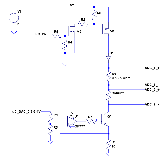
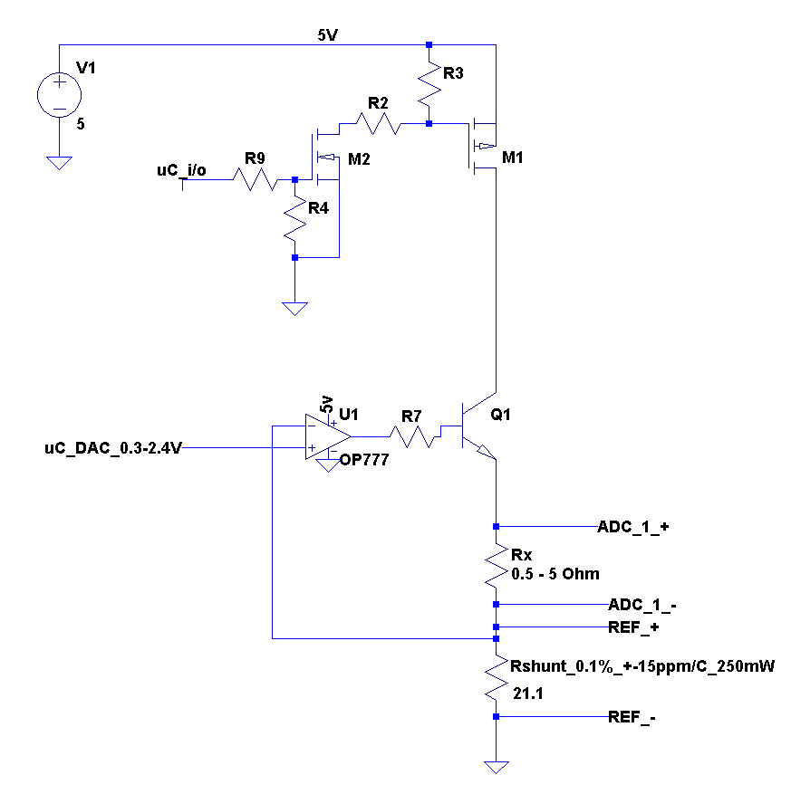
The schematic below shows the setup I planned. The High side mosfet is to switch on and of the current path, and the opamp, R1 and the NPN transitor control the current and can be set trough an DAC.

The Rx resistor will be outside the PCB and will be connected with 4 wires. Rshunt will be mounted on the PCB to measure the test current.

I would like to know if the setup I designed is feasible or is completely garbage.

Kind Regards, Johannes


  • Hi Johannes,

    Welcome to the TI E2E Forums!

    I think you're idea is reasonable... The ADS1262's multiplexer wouldn't be the main cause of delay when switching between two channels; the digital filter and the programmed data rate would be the biggest source of delay. So long as your current source is stable and doesn't change amplitude between the measurements, you probably wouldn't have any issues.

    However, instead of performing a second ADC measurement to determine the amplitude of the current source, I would recommend using Rshunt to create the external reference voltage to source to the ADC. By using this voltage as the ADC's reference, you create a truly ratiometric measurement that is independent from any change in current. Since the ADC compares its input voltage to its reference voltage, you're effectively measuring both inputs simultaneously. Rshunt would need to be a precision resistor on the order of 10 to 500 ohms, such that the voltage drop across this resistor exceeds the minimum 0.9V reference voltage requirement and also does not exceed the ~5V maximum reference voltage.

    Your current, current source implementation would probably work, but here are some other possible implementations from another E2E thread:
    https://e2e.ti.com/support/amplifiers/precision_amplifiers/int-precision_amplifiers/f/16/p/140361/506445#506445

    Perhaps you could even use some combination of the ADS1262's internal IDACs and an op-amp to create a programmable current source, for example, forcing the IDAC current through R5 to change the current through Q1.

    Best regards,
    Chris

  • Hello Chris, 

    Thank you for the feedback.

    I changed the design a bit to do a ratiometric measurement. 

    I also shifted the transitor to the top and am now using the precision reference resistor for the current feedback into the opamp.

    by the way, the link in your post, to different current supply methods does not work.

    With the 21.1 Ohm resistor the current range will be limited by the ADC min ref voltage of 0.9V and the max power of the resistor. 

    so the minimum test current will be 0.9V/21.1ohm = 42.7 mA

    and the maximum test current will be sqr(250mw/21.1) = 108.9 mA

    To create the powersupply for the analog circuit I am planning to use an LDO, to convert 12V from a DC/DC converter to 5V for the analog circuit. is there a specific LDO that you would recommend.  The Digital part of the ADC will be powered from a 3.3V LDO of an Microcontroller dev board.

    With Kind regards, Johannes

  • Hi Johannes,

    That looks looks good to me!

    Sorry about the previous link... I updated my last post to convert the URL to plain text.

    You should be able to use the ADS1262's PGA in a gain of 4 V/V for all input ranges. However, for the smaller values of R you could increase the gain to utilize more of the ADC's input range if needed.

    Do you have any idea yet of which data rate you plan to run the ADS1262 at or of how much resolution you need in your system?

    For the current setting, I would recommend running it somewhere in the lower or mid-range of what is acceptable (maybe in the 50 - 80 mA range). This way, you're not likely to fall below the 0.9V minimum reference voltage requirement and you also keep self-heating of the resistors to a minimum.

    Best regards,
    Chris
  • One more thing....

    For the LDO, I did a quick search and found that the LP2985 (with a shutdown option) or the LP2992 (if you need a bit more current) might be good solutions to take your 12V supply down to 5V.

    Best regards,
    Chris