This thread has been locked.

If you have a related question, please click the "Ask a related question" button in the top right corner. The newly created question will be automatically linked to this question.

ADS1299: DRDY always high and and DOUT always LOW preventing register reading and data collection

Part Number: ADS1299

Hi,

We are interfacing a ADS1299 with a Raspberry Pi by using a ADS1299 chip socket soldered to a perfboard with headers. We have connected the DIN, DOUT, CS, SCLK, PWDN, RESET, DRDY pins to the Raspberry Pi for control. We have confirmed and tested all of the signals that we send to the chip, but are currently unable to get a response on the DRDY or DOUT pins. We have already tested on two different ADS1299 chips, to no avail.

We have two questions:

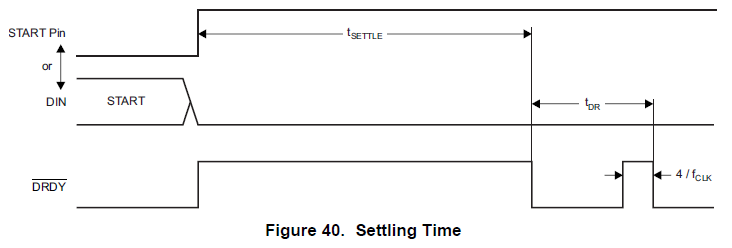
1) What is the expected state of the DRDY pin before performing the bootup sequence and sending the START command? Our DRDY pin always goes HIGH (3.3V) as soon as the power-supplies are turned on. Even after doing the power-up sequence and sending the START command, the DRDY line remains high, and does not pulse at all.

2) We are unable to get any activity or response on the DOUT output from the chip, which is always LOW. We have probed the line with an oscilloscope, and see no activity on the line. As a result, reading registers always return 0x00, and attempting to read the converted test signal data (albeit with the non-pulsing DRDY output described in 1) always returns 0. Does anyone have any idea what the issue may be? All other response we've seen on this forum have pointed to disconnected power supply pins as the issue, however, we have already confirmed that ours are correct.

Our configuration is:

- Unipolar power supply configuration as per Figure 77 in the ADS1299 datasheet

- START pin tied low (we will start conversions by sending the START command)

- CLKSEL tied HIGH to use the internal clock oscillator

- Using internal reference, so we are writing to CONFIG3 register upon bootup to write PD_REFBUF to 1

- Raspberry Pi GND, ADS1299 DGND and AVSS are all tied together

In our testing we have confirmed:

- VCAP1 charges to > 1.1V when power supplies are on and RESET is HIGH, and discharges when power supplies turn off

- All supply pins are at the correct voltages

- PWDN and RESET pins follow the power-up sequence

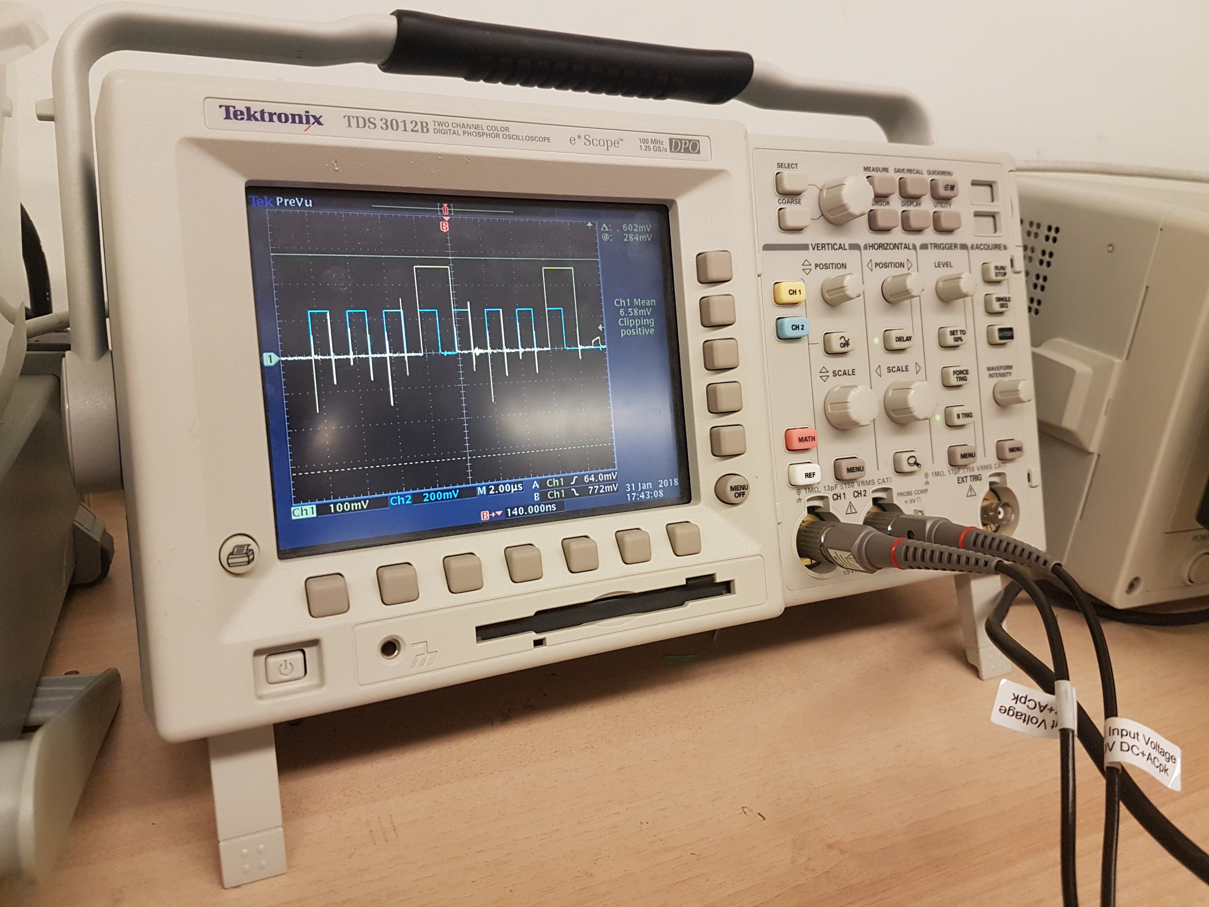
- The SPI outputs from the Raspberry Pi (MOSI, CS, and SCLK) behave properly. Below is an image of the SDATAC (0x11) command, with blue being SCLK, and yellow begin the MOSI (DIN) line.

Any help would be greatly appreciated.

Regards,

Albert Le

  • Hi Albert,

    Thanks for your post and welcome to our forum!

    I've noticed that the scale on your oscilloscope is much smaller than expected. Your SCLK appears to be 240 mVpp and the signal on DIN is only 260 mVpp. These signals should have an amplitude equal to DVDD. It's likely that the device is not recognizing the difference between a logic 0 and a logic 1.

    Are you sharing your ground connections between the ADS1299 and the Raspberry Pi?

    Best Regards,

  • Hi Ryan,

    Thanks for reply and suggestions. Albert and I are in the same team.

    Just wanted to update the thread, I think the scaling on the oscilloscope channels are due to probe settings (i.e 1x and 10x), sorry about that.

    The value for the channel 1&2 are 2.6 V and 2.4 V respectively. 

    Given that takes the former issue out of equation, do you have further suggestion or recommendation for us ?


    Cheers,
    Ramin 

  • Hi Ramin,

    Those amplitudes are still too low - they should reach much closer to DVDD. For DVDD = 3.3 V, the minimum amplitude required to register as a logic 1 is 0.8 * 3.3 V = 2.64 V.

    I did see that your first post mentioned connecting the grounds together, so that's good. Is the connection low impedance? Do you measure any potential difference between the two boards? If not, then something appears to be loading the SPI pins and preventing them from toggling between GND and DVDD.


    Regards,

  • Hi Ryan,

    I see your point now, makes sense (2.64v requirement as high).

    I did see that your first post mentioned connecting the grounds together, so that's good. Is the connection low impedance?

    I believe it is.

    Do you measure any potential difference between the two boards? 

    Yes we do.

    if not, then something appears to be loading the SPI pins and preventing them from toggling between GND and DVDD.

    I see, thats great point. We will check back and let you know. 

    Thanks for great help and your time on this!


    BR,

    Ramin

  • Hi Ryan,

    We rechecked all the connections between the Raspberry Pi and ADS1299 today and confirmed that their amplitudes were 3.3V with the exception of DRDY, which was 2.73 V due to a resistor we have between the chip and the Raspberry Pi. Our VCAP1 charges up to 1.9V upon power-up. Unfortunately, we still do not see any activity on the MISO (DOUT) line. Do you have any other suggestions? Also, is the high DRDY immediately after applying the power supplies expected, or should it only go high after sending the START command?

    Thanks,
    Albert
  • Hi Albert,

    After power-up, the /DRDY pin should only transition high after either the START pin is pulled high or the START command is sent. Please see Figure 40:

    Best Regards,