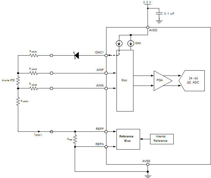
I'm trying do design low range, high precision temperature reader.
My design parameters:
|
DESIGN PARAMETER |
VALUE |
|
ADC supply voltage |
4.75 V (minimum) |
|
RTD sensor type |
4-wire Pt1000 |
|
RTD resistance range |
1038 Ω to 1175 Ω |
|
RTD lead resistance range |
0 Ω to 2 Ω |
|
RTD self heating |
1 mW |
|
Accuracy (1) |
±0.0002 Ω |
So based on ADS1262 datasheet I found that:
Idac1 = 0.5mA
Rref = 4,7kOhm
Rbias = 3,3kOhm
Rrtdmin = 1039 (10C)
Rrtdmax = 1175 (45C)
Vrtdmin = Idac1 * 1038 = 0.519V
Vrtdmax = Idac1 * 1175 = 0.587V
|
PGA1 Inputs & Gain |
||
|
VIN_P* |
2,237 |
V |
|
VIN_N* |
1,65 |
V |
|
PGA1 Gain |
4 |
V/V |
|
Supply Voltage(s) |
||
|
AVDD |
5 |
V |
|
AVSS |
0 |
V |
|
Reference Voltage(s) |
||
|
VREF_P |
4,587 |
V |
|
VREF_N |
2,237 |
V |
But in all calculation I only used Vrtdmax, and I have that feeling that I'm not using full range of my ADC - especially from range 0-1038 Ohm ..I just not using this.
Is there any way to shift levels to only measure zoomed resistance range from 1038 Ω to 1175 Ω ?
My design is just simple as IN0(IDAC1) > IN2 > Rref > IN3 > IN6 > RTD > IN7 > Rbias > GND
I am using ADS1262EVM-PDK for testing
BTW, there is a typo in ADS1262 data sheet: before Equation 31 there is -
VREFMIN = 0.2 V · 4 = 1.6 V
it should be
VREFMIN = 0.2 V · 8 = 1.6 V


