This thread has been locked.

If you have a related question, please click the "Ask a related question" button in the top right corner. The newly created question will be automatically linked to this question.

DAC8742HEVM: Problem with generating valid master request via DAC8742HEVM GUI

Part Number: DAC8742HEVM
Other Parts Discussed in Thread: USB2ANY, DAC8740H, DAC8742H, ENERGIA

Hello,

I'm using DAC8742HEVM with SPI & HART interface and I would like to generate master request to my sensor (SEM315 MKII with PT100) - preferably sending HART command 0 using the board & GUI. The problem is that DAC8742HEVM GUI is insufficiently documented and creating valid HART frame seems to be a problem. There is no information on how HART frame is created via GUI. I've tried sending data on multiple ways - starting from preambles, delimimiter etc. Seems that 'raw' frame should be correct (from preambles to the check byte), but unfortunatelly sensor could not respond to that.
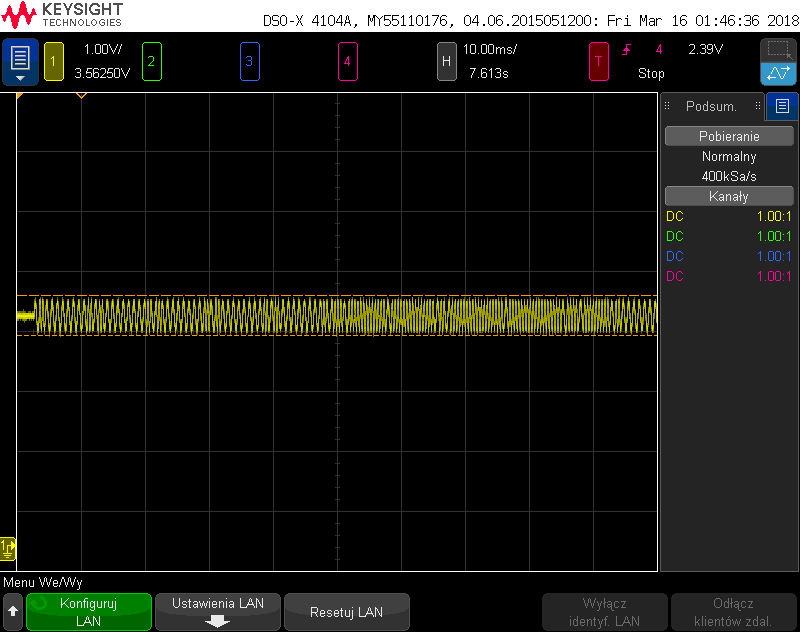
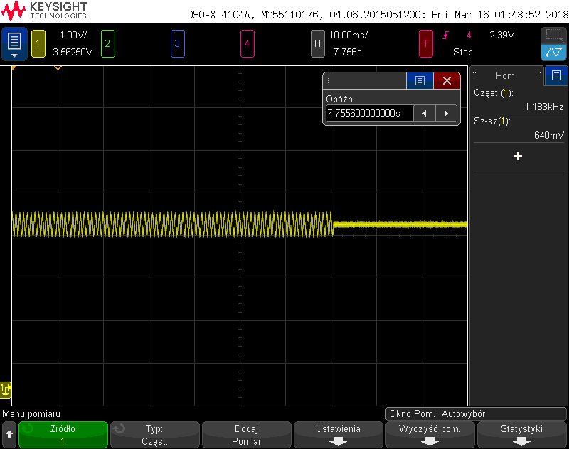
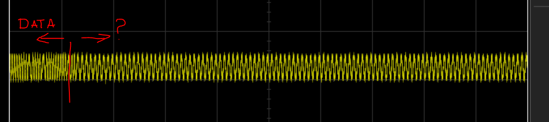
I can observe message on the oscilloscope and it looks like that after HART frame there are added a lot of ones, could that be the problem?

I would really appreciate some additional documentation of the tool or some valid working examples.


Best regards

  • alt,

    We appear to have received the same inquiry via email from a TI FAE.

    Would you prefer to continue the discussion directly via email or here on the forum?
  • Hi Alt,

    The EVM software was targeted towered evaluating the physical / data link layers so it is not very convenient at the application layer. That being said, you should still be able to manually construct a HART message. The form of the message is:

    Delimiter|Address|Expansion|Command|Byte Count|Data|Check Byte

    Basically you would just put each byte in the left hand column and it will transmit. Then click 'Generate read' and the right hand column will show you the response if the HART message you sent was valid. Is this what you tried? If the sent message is not correct you will not receive a reply. In the image below I connect the input to the output and turn on full duplex to read the transmitted data back. I set it to UART mode:

    Are you able to read back in full duplex mode? I would try this first.

    I would recommend setting the EVM to UART mode as there is a 15 byte message limit using SPI with this software. In UART mode you must specify a number of bytes to read. Essentially the USB2ANY reads in the UART continuously and clicking read retrieves it from memory. In my read back setup I have the reference turned on, the BPF enabled, and UART turned on.

    I left all the jumpers on the board in their default locations.

    Let me know if you try this and still don't get a response from your field device.

    Thanks,
    Garrett

  • Garrett Satterfield said:

    The form of the message is:

    Delimiter|Address|Expansion|Command|Byte Count|Data|Check Byte

    What about preambles? From what I could see on the oscilloscope this should be taken care of manually. As far as I know start of message in HART protocol is two consecutive 0xFF's followed by valid Delimiter, therefore I assume that it should be included in "HART/PAFF write" fields in order to communicate properly. Is this correct?


    Garrett Satterfield said:

    Basically you would just put each byte in the left hand column and it will transmit. Then click 'Generate read' and the right hand column will show you the response if the HART message you sent was valid. Is this what you tried? 

    Yes, this is exactly what I've tried. I've tried to send '0' command using short frame and polling address (same as set on the slave device).
    In SPI mode after sending request (or even random data) I've got '0x200' after clicking generate read, but as I said no response from the slave could be observed on the oscilloscope. Based on the HART specification seems that '0x20' is overrun error or some kind of power failure, but command status bytes should be included in the response, therefore I'm not sure if this '0x200' is actually an error.


    Garrett Satterfield said:

    Are you able to read back in full duplex mode? I would try this first.

    Yes, after connecting HART_IN with HART_OUT I've got same data as expected in full duplex and half duplex mode.


    I also tried to send hart frame using UART and in case where there are preambles included GUI exits and on the oscilloscope continuous ones are observed until GUI is again started, also after that after reading registers all are FFFF's.

  • Hi Alt,

    Yes you are correct, a 5-20 byte long preamble is used before the message frame.

    I looked up the SEM315 MKII device and found that it is a two wire current loop device. If this is the case the device requires loop current to operate and the HART signal modulated on top of the DC current. It would not work to use the device directly with the EVM. Can you explain how you are interfacing the EVM to the 2-wire device? Are you using the EVM to modulate the loop current?

    Thanks,
    Garrett

  • SEM315 MKII is powered from external power supply (24V) it also has load connected in series (>=250 ohm) to allow HART communication. I wanted to use EVM as HART modem, so it is connected in parallel with the transmitter via MOD_IN & MOD_OUT.

  • Hi Alt,

    Can you include a schematic/diagram of how you are connecting the EVM to your current loop?

    Thanks,
    Garrett
  • Currently I've got MOD_OUT connected to + and MOD_IN to -, also tried switching it but there is still no response from the sensor.

  • Hi Alt,

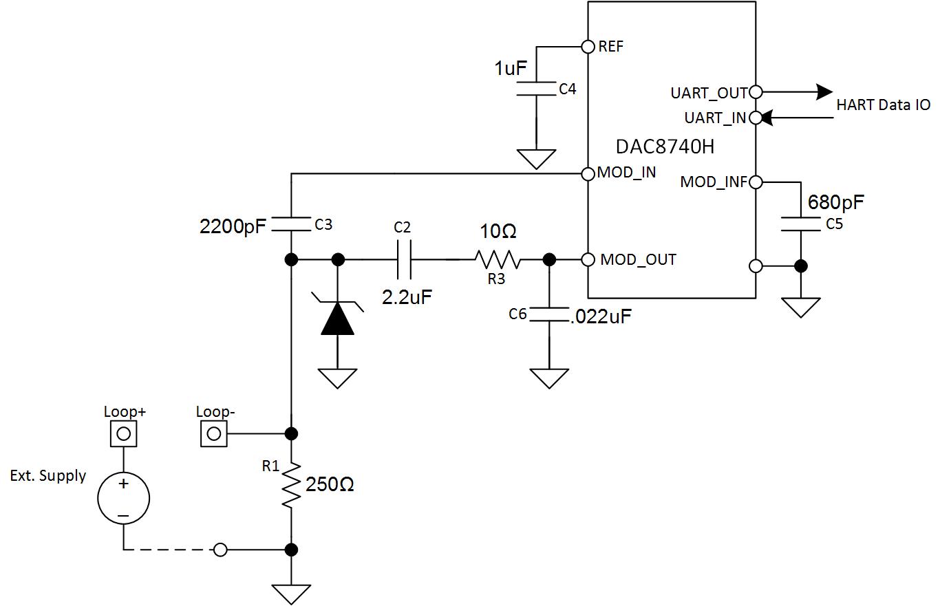
    Both MOD_IN and MOD_OUT of the DAC8740H should be AC coupled to the load resistor node. In your diagram MOD_OUT is connected directly to the power supply. Refer to Figure 32 of the DAC8740H data sheet that shows the coupling capacitors on MOD_IN and MOD_OUT.

    Thanks,
    Garrett
  • Garrett,

    So you are suggesting to connect both MOD_IN & MOD_OUT to one node of the resistor nodes, is that correct? Could you provide diagram of recommended connections?

    I think that if my previous connections were wrong, the EVM would not be able to generate any HART signal at all. However, the generated signal always lasts for the same amount of time, no matter how many bytes I specify in "HART/PAFF Write" fields.The remaining part of the message is composed of ones, as shown below. Is this an expected behaviour? Perhaps this may results in inability of slave device to properly recognize the message? 


    Regards

  • Hi Alt,

    Yes, in the analog input case both MOD_IN and MOD_OUT should be AC coupled to the same node on the load resistor. I have included a diagram of the HART portion of an analog input module. Connecting both input and output to the same node will also let you read back in full-duplex mode so you can ensure the modem is modulating/demodulating correctly.

    The waveform length should be dependent on how many bytes are sent with each byte taking about 6.7ms to send. The capture you provided appears to be 40 bytes long. How many bytes did you specify? Are you using UART or SPI to transmit the HART data? Do you get the correct data if you read back in full-duplex mode with the input and output tied together? Is the EVM in the default configuration specified in the user guide?

    Thanks,
    Garrett

  • Hi Garrett,


    When both MOD_IN & MOD_OUT are connected to the one node of the resistor & UART is selected same data could be read via GUI (this is same as test which you suggested to do on 13 Mar). I was sending 10 bytes via UART, board is in the defult configuration as specified in the user guide.
    This assures that EVM is able to demodulate its own signal. This unfortunately does not solve problem with communication with field device.

    First capture from previous post shows 10 bytes of data which were intended to be send and were specified in GUI. Second capture shows end of specified data and start of those ones which seem to be added without users control.

  • Hi Alt,

    I was able to replicate this issue in the lab. This issue is caused by a limitation of the software platform of the EVM. There is a delay between when the data is written and when the RTS pin or RTS bit (SPI) is toggled. This causes the modulator to keep modulating ones until the RTS pin/BIT is toggled resulting in many ones after the intended data like you have seen. As I stated earlier the EVM is more for evaluation of the physical layer and is not really intended to directly communicate with field devices.

    That being said, I don't think this 'padding' of ones after the message frame will cause the device not to respond. Since the start bit would have to go to zero before the field device starts acknowledging the valid data. I would expect the field device to simply wait until the carrier stops and then reply based on the data sent before all the ones. This would cause a delay but I would still expect a response.

    I was also wondering if there is another way to make the field transmitter transmit a HART message. Then you could measure the signal on the load resistor and ensure that the signal amplitude is correct for the DAC8740H to demodulate. If it is the correct amplitude then you could connect the DAC8740H and the message should demodulate. Is it possible to make the SEM15 MKII transmit HART onto the current loop with the USB interface used for configuration?

    Thanks,
    Garrett

  • Hi Aleksandra,

    I wanted to provide a recap of the issue and recommended solution. 

    The problem is due to limitations of the EVM software. The delay between writing data and toggling RTS causes extra transmission of the 1200Hz signal for several hundred milliseconds. This cause ones to be padded onto the data as the modem keeps modulating until RTS is toggled. You suspect that this is why the field transmitter does not respond because it reaches a timeout and discards the data. We will look into fixing this issue in the EVM software in the future but it may take some time to solve.

    I think a quicker solution for you will be to use a microcontroller to transmit the HART data to the DAC8742H via SPI/UART. This will remove the delay between the transmitted data and RTS toggling. It should be fairly straight forward to accomplish this with an MSP430 launchpad or similar microcontroller. If you have not used the MSP430 launchpad platform before it may want to use the Energia IDE as it is easy to start with. There are many tutorials on using SPI/UART with Energia.

    You can use either SPI or UART. In UART mode the modem acts as a UART to HART feed through converter. UART/SPI modes are selected by the IF_SEL pin.

    The transmission process for UART is simply:

    1. Pull down RTS pin.

    2. Transmit UART data at 1200bps.

    3. Pull up RTS pin.

    4. Receive response data.

    You can use either SPI or UART but operating in UART mode is somewhat simpler. Let me know if you have any questions on this solution.

    Thanks,

    Garrett

  • Hello,

    This conversation has been taken to email.

    For future readers - if you have further inquiries please feel free to make a new post / thread. In short, this is a limitation of the EVM GUI - not the device - which we will be working to address.

    Thanks!