This thread has been locked.

If you have a related question, please click the "Ask a related question" button in the top right corner. The newly created question will be automatically linked to this question.

ADS8688: TIDU365B–Revised September 2014

Part Number: ADS8688

Hi Supporter

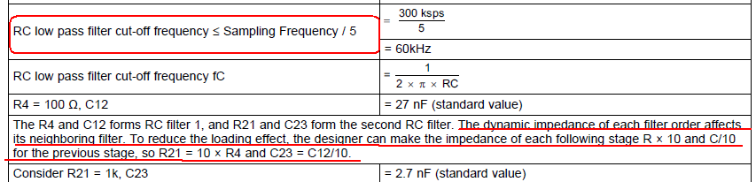
TIDU365B–Revised September 2014  design guide shows below. Could you help explain why RC low pass filter cut-off frequency samller than sampling frequency/5? Why impedance of following stage R*10 and C/10 for the previous stage?

Regards

David

  • Hi David,

    Thanks for your query on E2E. Since this reference design was designed by our system team, so I have assigned this thread to SANKAR SADASIVAM who is Chief Technologist for Industrial Systems Engineering at Texas Instruments, he will be able to answer your questions.

    Thanks.

    Best regards

    Dale

  • Hi David,

    The RC filter cut-off frequency is chosen such a way that the aliased frequency component levels are low. The aliased component values depend on the order of the filter and the cut-off frequency chosen. In this design a simple 2 stage cascaded RC filter design is chosen as a trade-off between filter roll-off and cut-off frequency. The second stage R and C values are chosen such a way to avoid loading of first stage filter and make the calculations simple. However this can be improved by using filter calculation tools to get better filter responses without the constraint of 10x Resistor values.

    regards

    Sankar