This thread has been locked.

If you have a related question, please click the "Ask a related question" button in the top right corner. The newly created question will be automatically linked to this question.

WEBENCH® Tools/PGA900: PGA900 4-20mA constant current output layout

Part Number: PGA900

Tool/software: WEBENCH® Design Tools

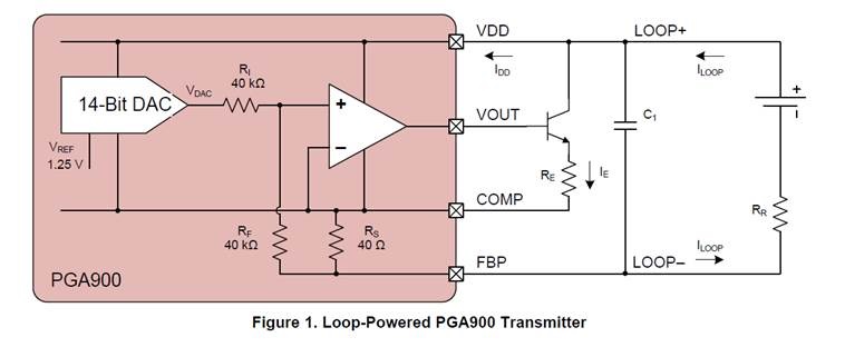
according to the detail explain for "PGA900 as a 4- to 20-mA Current Loop Transmitter" document 

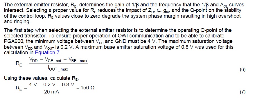
I just want make sure the equation (7) to evaluate the resistor value for my layout is correct or not?

in my PCB layout the VDD is 24V, so the RE is (24V-0.2V-0.8V)/20mA=1150 Omh

Is that right?

thanks 


  • Hello,

    There is one thing that this equation does not take into account, which is the 40 Ohm internal resistance between COMP and FBP. The device ground (COMP) is separated from the current loop by the 40 Ohm resistance. So the actual VDD you should be using is VDD -- IOUT_MAX*40. Additionally I suggest that you size the resistor based on the minimum possible VDD, and the maximum expected Iout + some margin. For typical 4-20mA operation I would suggest a margin of 5-10mA.

    Using your numbers with a new Ioutmax of 30mA:

    VDD = 24 -- (.03)*40 = 22.8 V

    (22.8V - 0.2V - 0.8V) / 30mA = ~726 Ohm

    Regards,
  • thanks for your reply.