This thread has been locked.

If you have a related question, please click the "Ask a related question" button in the top right corner. The newly created question will be automatically linked to this question.

DAC8760: VSENSE Inputs

Part Number: DAC8760
Other Parts Discussed in Thread: DAC8771, INA826

Hello.

I am planning to use the DAC8760 in a new design for industrial analogue output, that can be configured for either 10 V or 20 mA output. Here the DAC8760 seems to fit perfectly.

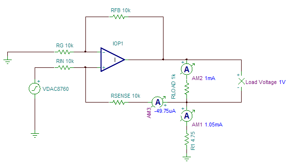
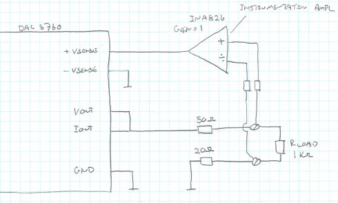
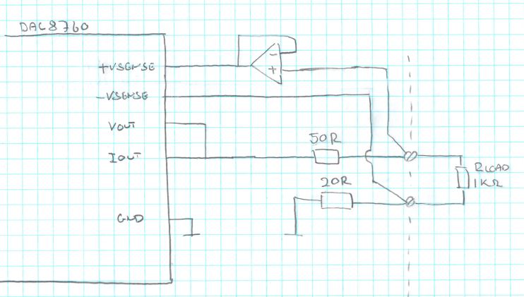
I have to put some filters in the output. These filters gives an ohmic resistance for 50R and 20R as shown in the schematic drawing below.

In voltage output mode the 20R resistance will give 0,2% failure when the output is 10V with a 1 Kohm load, so I was planning to use the -VSENSE input to compensate for this error.

My question is if it is the correct way to use the -VSENSE pin. The datasheet says that the voltage level on this pin should only be a few µV from the GND, but in this case it will be up to 200mV. Is this to high? On all reference design I can find, the -VSENSE pin is connected to GND.

Best regards

Niels Ole Jørgensen

  • Hello Niels,

    Could you elaborate on the filter and why this is adding a series impedance between the load impedance and ground?

    If this is a requirement, then indeed this is a shortcoming of the -VSENSE pin, in fact as is shown on Figure 83 in the datasheet there is actually a 2kOhm (+/-20%) resistor to ground as opposed to a real sense connection. So the internal DAC circuits would not help compensate for the loss of accuracy.

    It's probably also worth mentioning that for applications which share a single connection for IOUT and VOUT, there are some accuracy concerns as well due to the exposed sense resistor connections on +VSENSE. There is an application note which explains both a SW and HW method of compensation - the HW method is best as it preserves integrity at the end-points which are not possible to compensate for in SW.

    In order to compensate for the resistance in series with the load and ground we could propose a relatively simple difference amplifier circuit and/or the use of an instrumentation amplifier. We would still need to be mindful of leakage current for the IOUT, though and the fact that we would need an amplifier or INA with a shut-down feature which actually leaves the output and input terminals high-z. If the amplifier is out of the picture in shut-down mode we could partially compensate for leakage with increased resistors sizes versus what I had in this older diagram along with the SW calibration technique.

    At a certain point it may be easier to consider DAC8771 for this implementation as the VSENSEN pin functions as you desire in this application with up to 7V separate / compensation. Furthermore the VSENSEP connection is severed when the VOUT is inactive, so additionally the IOUT leakage issues go away. The device also brings additional capability to the application with the integrated buck-boost converters.

  • Hello Kevin


    Thanks for the quick reply.

    I think that I will change the design, so that instead of the operational amplifier for the +SENSE input I will use an instrumentational amplifier like INA826 with the gain set to 1. The input to the instrumentional amplifier will be measuring above the output terminals on my design, and the output set to the +VSENSE input on the DAC

    In this way the error caused by the 20R resistor should be eliminated, and still the current output and the output impedance will not be affected

    Please comment if this is correct.


    Best regards


    Niels Ole
  • Niels,

    Just so we can be clear and aligned, can you maybe make a quick drawing of your proposal? I just want to make sure my understanding / visualization of your proposal is correct...

    Pretty sure you're looking to put +IN at the high-side of your load and -IN at the low side of the load with the differential Vo voltage connected across +VSENSEP and GND.

    I think that should be reasonable as well.

  • Hi Kevin

    Below is a drawing off my porposal.

    The idea is to measure the voltage above the load with the instrumentational amplifier, and send the output from the amplifier to the +VSENSE pin on the DAC8760.

    Best regards

    Niels Ole 

  • Hi Neils,

    Thanks.

    This is what I expected to see. I think this should be a good solution.