This thread has been locked.

If you have a related question, please click the "Ask a related question" button in the top right corner. The newly created question will be automatically linked to this question.

ADS1274: Gain dependent on sampling frequency and number of active channels

Part Number: ADS1274

On our board we use the ads1274 for doing data acquisition on maximum 4 channels. We see however a problem related to the gain.

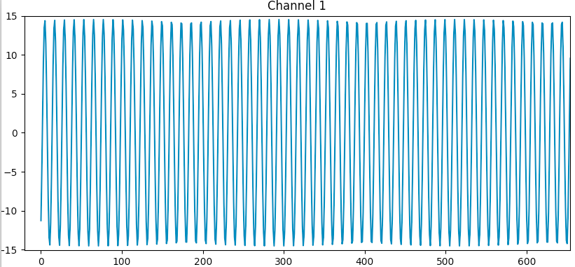
When we supply a 10kHz input signal when 1 channel is active we see a constant level/gain when going from a sampling frequency from 30 kHz to 120 kHz.

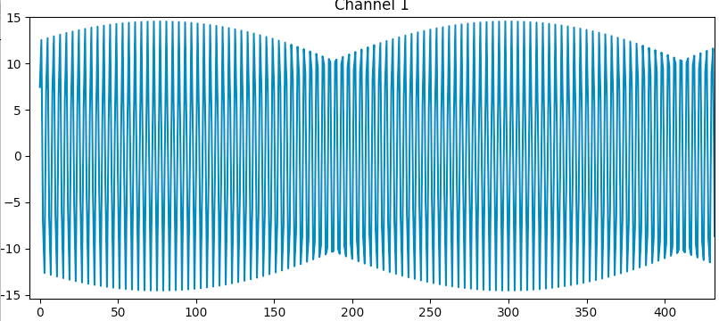
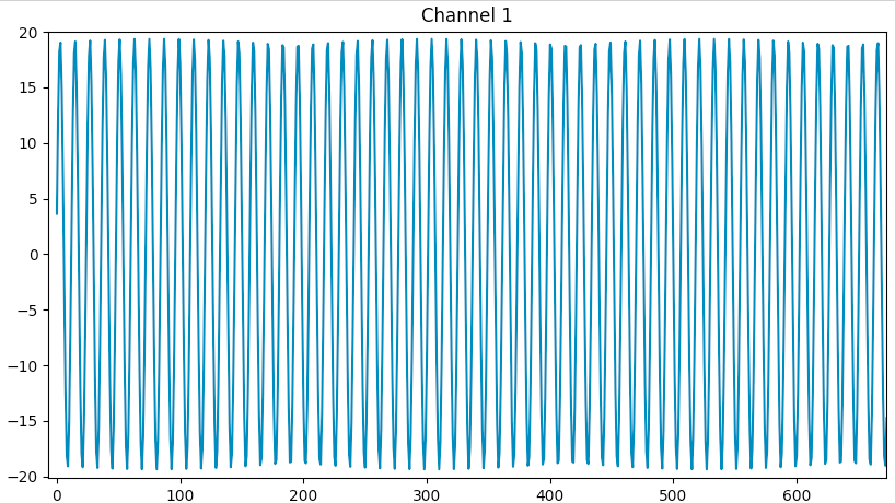
However when we supply the same input channel on one channel but now with all 4 channels active we see the gain increasing when the sampling frequency is higher then 70 kHz (see table)

Sampling frequency        Amplitude of recorded signal (relative)

40k     1.00
50k     1.00
60k     1.00
70k     1.00
75k     1.03
80k     1.06
90k     1.13
100k   1.20
120k   1.34

Is dit a known problem? What could be the reason for this? Can this be avoided and/or compensated?

  • Hi Marc,

    Welcome to our forum and thanks for your post!

    Can you give us the configuration of the ADS1274 (CLK input frequency, MODE, and FORMAT settings)? Are you scaling the CLK input in order to produce different data rates and leaving the MODE the same?

    The digital filter features a flat, unity-gain passband until about 0.453*fDATA. Increasing the data rate should only extend this passband and have no effect on the signal gain.

    How are you measuring the relative peak amplitude? If you are simply observing the maximum point in given signal period, you may be catching a spike in the noise, which will increase as you increase the digital filter bandwidth. However, I imagine that effect should be the same regardless of the number of active channels.

    Can you share a plot of the data you've collected for 40 kSPS and 120 kSPS?

    Best Regards,
  • The ADS1274 is always in High-Speed MODE.
    The FORMAT is 011
    The CLK depends on the selected sampling frequency: 256*fSam

    I am calculating the RMS value of the signal to compare the level of the recorded signals.

    In the 3 recordings below, the same input signal was applied (a sine wave of 10k)

    The exact sampling frequencies are 40178.6 Hz and 120535.7 Hz.

    Signal recorded at 40k (the same for 1 and 4 channels active)

    Signal recorder at 120k with 1 channel active:

    Signal recorded at 120k with 4 channels active:

  • Hi Marc,

    Please excuse my delay.

    First, the unique shape of the 10kHz sine wave sampled on Channel 1 at 40kSPS is likely the result of undersampling. Although you are satisfying the Nyquist criterion of fs > 2x fin, the amplitude of the original input may not be accurately represented with only 4 samples per period.

    I believe the change in signal amplitude may be the result of the changing input impedance on the reference voltage input. Your external reference circuit is connected directly to the internal switch-capacitor sampling structure shown in Figure 71 of the datasheet. As the master CLK frequency increases and as the number of active channels increases, the effective input impedance will decrease. If your external drive circuitry does not adequately maintain a constant reference voltage, the gain error term in the ADC transfer function will be worse.

    For one active channel @ 40kSPS: Zeff = 13.65k Ohms

    For four active channels @ 40kSPS: Zeff = 3.41k Ohms

    For one active channel @ 120kSPS: Zeff = 4.55k Ohms

    For four active channels @ 120kSPS: Zeff = 1.14k Ohms

    Can you please share a schematic of your ADS1274 circuit with input and reference drive circuitry? If you prefer to send it to me offline, I can contact you via the email address in your profile.

    Best Regards,

  • OK, I suggest that you contact me via e-mail.

    Best regards,

    Marc

  • Thread closed. Reference circuit was reviewed offline.

    Regards,