This thread has been locked.

If you have a related question, please click the "Ask a related question" button in the top right corner. The newly created question will be automatically linked to this question.

ADS8363: ADS8363 MSB is always zero

Part Number: ADS8363
Other Parts Discussed in Thread: ADS8353, ADS8860, ADS8332

I had some initial problems with the ADS8363 which were related to the timing between the Rd pulse and the clock pulse. I changed that timing which kind of solved the problem. The reading tracks very well from 0 to 32,768, but the most significant bit is always zero. In that application 15 bits was adequate, but now I am using the ADS8363 in an application that requires 16 bit accuracy. I am interfacing the ADS8363 with an STM32F407 processor and uses the standard SPI hardware and a separate port to pulse Rd. Using a separate port I have not been able to generate an Rd pulse that meets the requirement of less than 1 clock pulse. My Rd starts about 200nS before the first clock and ends about 10nS before the rise of the second clock pulse, see attached logic analyzer capture. This seems to work very well, but may be what is causing the MSB to always be zero. However, if the input is a few millivolts below zero the MSB then goes high. Could the Rd timing be what is causing my MSB to always be zero?

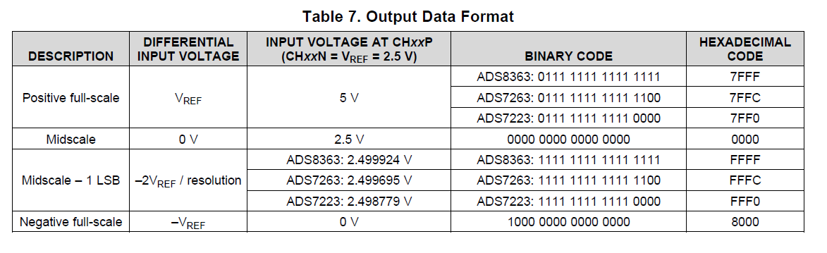
The ADS8363 is in Mode 1V, the negative inputs of the ADCs are all grounded and the positive inputs are used as single ended inputs. The reference voltage is 2.5V. With an input of +2.5V the reading is 32,676, which seem strange because if the Rd timing was the cause of the problem I would have expected the output to saturate at 32,768 with an input of 1.25V, not 2.5V.LogicPort Input = 2.5V.pdf

  • HI Bob,

    The ADS8363 is a 16-bit device supporting fully-differential or pseudo-differential inputs and produces conversion results in 2's complement format, where the CHxxP input can be negative with respect to CMx or CHxxN.  The positive/negative full-scale range is ± VREF.  Since the device supports differential inputs, the MSB works as a sign bit.

    Essentially the ADC converts the difference between CHxxP and CHxxN (or CHxxP and CMx) and provides the 16-Bit conversion results in 2's complement format.

    For example, Table 7 shows the expected code results while holding CHxxN=VREF=2.5V.  In this case, the device provides full-scale positive when CHxxP=5V, where the ADC sees positive full-scale (+2.5V) and the resulting code is 0x7FFF. The device produces negative full-scale when CHxxP=0V, where the ADC sees negative full-scale (-2.5V) and the resulting code is 0x8000.

    In your case, if CHxxN is fixed at GND, the device is only using 1/2 of its range, and produces positive full-scale at +2.5V with a code of 7FFF (or 32767). 

    If you are interested in obtaining 16-bit conversion results from 0 to 2.5V, one possibility may be to set up the device in pseudo-differential configuration, using an external reference of +1.25V and holding CHxxN at VREF=1.25V in pseudo-differential configuration. Another possibility is to use an ADC supporting single-ended inputs such as the ADS8353, ADS8860 or ADS8332.

    Thank you,

    Best Regards,

    Luis


  • Thanks Luis, your explanation was excellent, I wasn’t paying attention to “fully differential”. Once I understood it was easy to fix. I connected all of the negative inputs to the +2.5V reverence and corrected the readings in firmware. The input is now 0V to +5V and the range is full 16 bits.

    Thanks again for your help.
    Bob