Other Parts Discussed in Thread: ADS1292,
Hi:
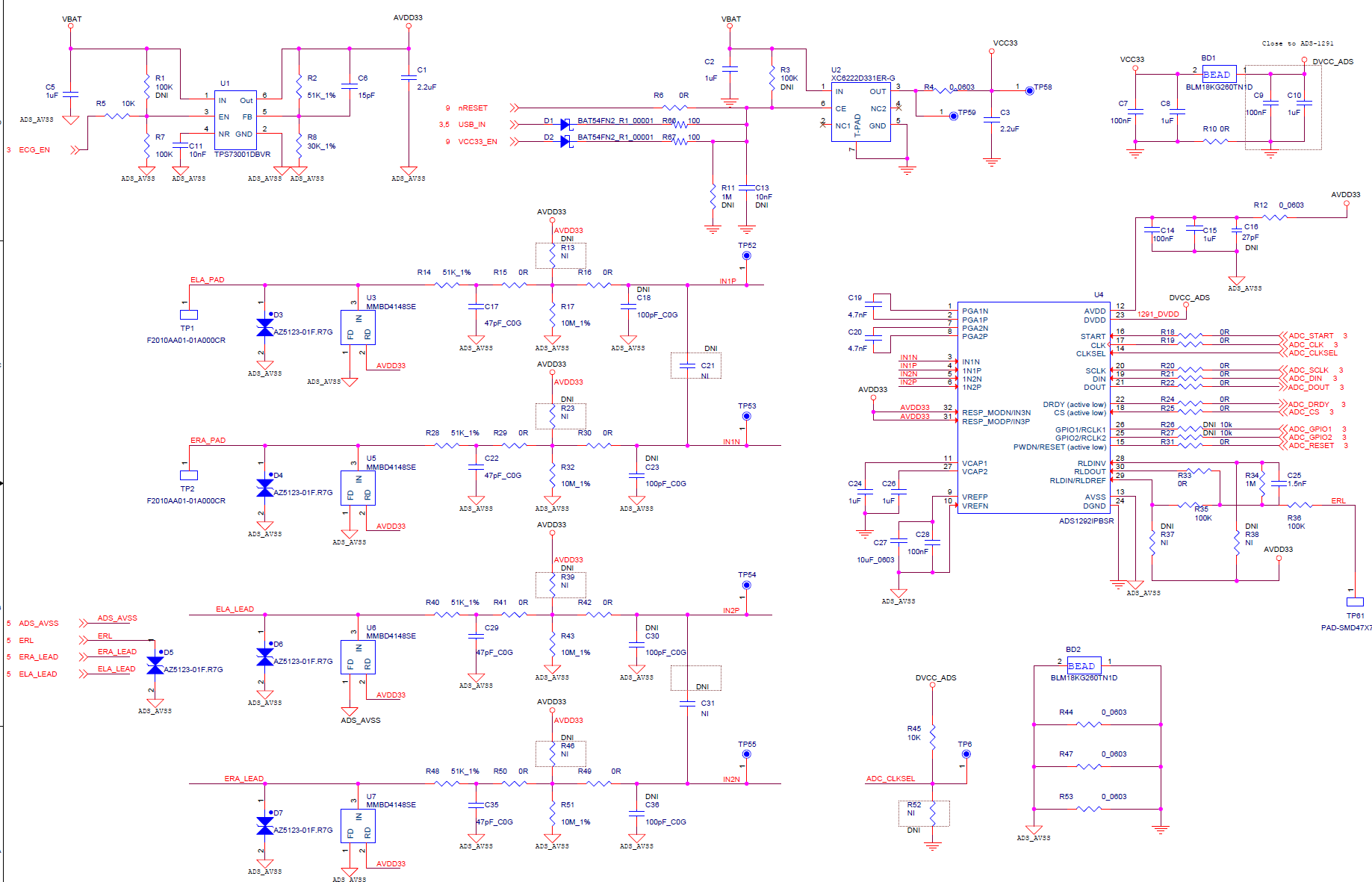
We have a device use the ADS1292 chip, we can read the ADC data correctly via the SPI bus when Lead wire is connected。
But we found the lead-off detect is invalid when the lead wires is disconnected, the state of register is unchanged. How can I get the correct state for lead-off detect?
The state of status register read after lead wires connected or disconnected show below:
CH1 CH2
P N P N
Lead wire disconnect 0 1 0 1
Lead wire connect 0 1 0 1
0-->connected; 1-->disconnected.
The ADS129's registers configure as below:
unsigned char ADS1292_Default_Register_Settings[12] = {
//Device ID read Ony
0x00,
//CONFIG1
0x02,
//CONFIG2
0xE0,
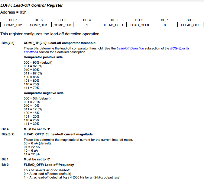
//LOFF
0x10,
//CH1SET (PGA gain = 6)
0x00,
//CH2SET (PGA gain = 6)
0x00,
//RLD_SENS (default)
0x20,
//LOFF_SENS (default)
0x3F,
//LOFF_STAT
0x00,
//RESP1
0x02,
//RESP2
0x07,
//GPIO
0x0C
};