This thread has been locked.

If you have a related question, please click the "Ask a related question" button in the top right corner. The newly created question will be automatically linked to this question.

DAC8760: DAC8760 interfacing with PSOC4 through Hardware SPI

Part Number: DAC8760

Hi,

        I need help in both hardware and Software. We have designed the board with PSOC 4 and DAC8760 to provide DAC output. But while Checking we got 700 milli Voltage from Refout Pin (which in turn connected to Refin pin). Can we give 5V directly to Refout Pin???

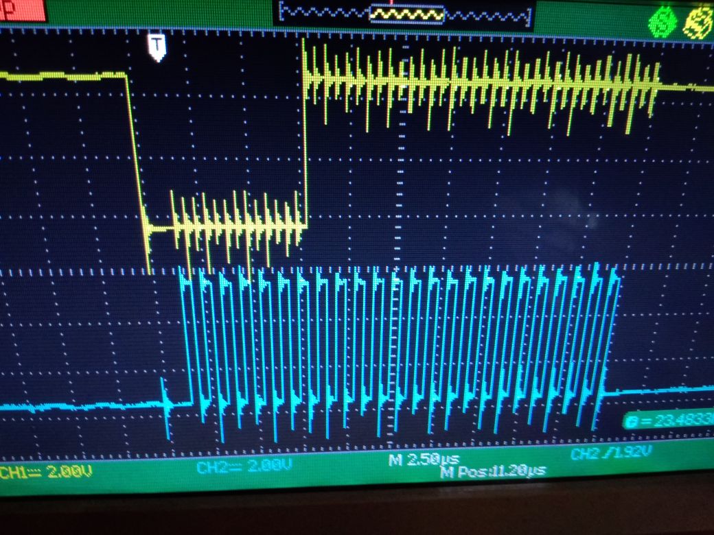
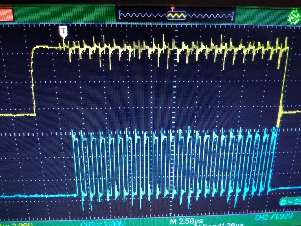
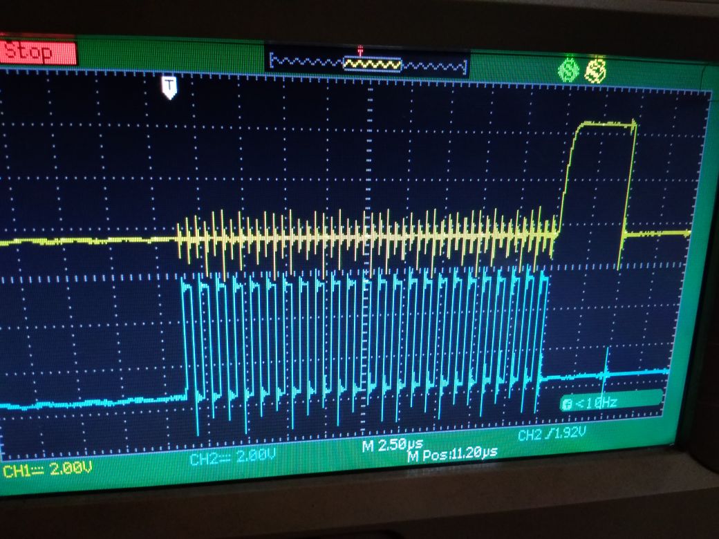
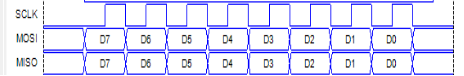
And below I have pasted my code in which the program uses Hardware SPI, even checked with the Oscilloscope that I have transmitted data Successfully but while attempting to read Can't read any data from register.

#include "project.h"
#include "stdio.h"

int main(void)
{
   
    int i=0,x,y;
    char str[10];
    CyGlobalIntEnable;
   
    SPI_Initialise();
   
    //SPI_1_SpiSetActiveSlaveSelect(SPI_1_SPI_SLAVE_SELECT0);
    //Slave Select as Seperate Pin SS_2
    //Resetting DAC8760
    SS_2_Write(1);
    SPI_1_SpiUartWriteTxData(0x56);
    CyDelayUs(SPI_Delay);
    SPI_1_SpiUartWriteTxData(0x00);
    CyDelayUs(SPI_Delay);
    SPI_1_SpiUartWriteTxData(0x01);
    CyDelayUs(50);
    SS_2_Write(0);
    CyDelayUs(SPI_Delay);
   
   
    //Writing First Initial data to DAC Data Register
    SS_2_Write(1);
    Clear_Write(1);
    SPI_1_SpiUartWriteTxData(0x01);
    Clear_Write(0);
    CyDelayUs(SPI_Delay);
    SPI_1_SpiUartWriteTxData(0x00);
    CyDelayUs(SPI_Delay);
    SPI_1_SpiUartWriteTxData(0x00);
    CyDelayUs(50);
   
    SS_2_Write(0);
   
    // Writing to the Control Register for 0 to 10 V Output
   
    SS_2_Write(1);
    SPI_1_SpiUartWriteTxData(0x55);
    CyDelayUs(SPI_Delay);
    SPI_1_SpiUartWriteTxData(0x10);
    CyDelayUs(SPI_Delay);
    SPI_1_SpiUartWriteTxData(0x01);
    CyDelayUs(50);
    SS_2_Write(0);
   
   
    CyDelay(1000);
   
   
    for(;;)
    {
        //Writing 10V Data to the DAC data Register
       
        SS_2_Write(1);
        Clear_Write(1);       
        SPI_1_SpiUartWriteTxData(0x01);
        Clear_Write(0);
        SPI_1_SpiUartWriteTxData(0xFF);
        SPI_1_SpiUartWriteTxData(0xFF);
        CyDelayUs(50);
        SS_2_Write(0);
        CyDelay(1000);
       
        //Writing 5V Data to the DAC data Register       
       
        SS_2_Write(1);
        Clear_Write(1);       
        SPI_1_SpiUartWriteTxData(0x01);
        Clear_Write(0);
        SPI_1_SpiUartWriteTxData(0x7F);
        SPI_1_SpiUartWriteTxData(0xFF);
        CyDelayUs(50);
        SS_2_Write(0);    
        CyDelay(1000);
    }
}

Thank You.

  • Hi Ranjith,

    Welcome to the E2E forums!

    To answer your first question, if you are using an external 5V reference it should be connected to REFIN. If you are using the internal reference then REFIN should be connected to REFOUT and the internal reference should be enabled.

    Looking at your code it appears that you are only sending 2 bytes in the SPI data frame. The device expects a 24 bit SPI frame that consists of an address byte followed by two bytes of data. It is required that 24 bits are sent before the rising edge of the LATCH pin for the data to be clocked into the device. I think this is your issue.

    If this doesn't resolve your issue it would be helpful if you could provide an oscilloscope capture of SCLK, DIN, and LATCH on the same capture to ensure the SPI frame is correct. Also, can you provide a schematic of your circuit?

    Thanks,
    Garrett

  • Hi Ranjith,

    My apologies, I misread your code previously. I see how you are sending three bytes with delays in between. I would still like to see an oscilloscope capture of the waveforms and a schematic if you can provide these. This will help validate your hardware setup as well as the SPI transaction.

    Thanks,

    Garrett

  • Hi Garrett,

        Thanks for your reply. I have attached for Latch, Clock and MOSI Pin out Oscilloscope images along with this post.

    DOUT with Clock

    Latch with Clock Before seeing your post

    Latch with Clock after editing

  • I have attached 5 V external Supply and Checked now I'm getting 4.5V as Constant but no change after writing on Data Register
  • Hi Garrett,

    I have attached the Clock and Data format from SPI Selection as in the attached image below.

    Thanks,

    Ranjith.

  • The Issue is not resolved even after giving that pulse I have not got any output on that Pin
  • Hi Ranjith,

    Thank you for providing waveforms.

    In your 3rd waveform you show the rising edge of LATCH after the 24th clock edge which looks correct but did you ever bring LATCH high beforehand? There is a minimum LATCH high time of 40ns so if you never bring it high it may cause an issue.

    When you say you attached a 5V supply does this mean you connected 5V to the reference? I know you said previously the reference was 700mV. It is concerning that the reference does not come up to 5V. Is it possible that you are shorting it somehow on your board?

    Can you provide a schematic to verify your hardware setup?

    Thanks,

    Garrett

  •  Hi Garrett,

        I have verified the hardware the Pins Refout & Refin Pins are shorted. Still no clue.

        Currently writing the data as first writing Control register to disable output and then continue on writing on 0x01 register and again in control register to enable the input.

  • Hi Ranjith,

    I looked over your schematic and do not see anything that would lead to this issue. Have you measured the voltage of the internal regulator DVDD? Does it come up to about 4.6V? 

    It seems like there is some hardware issue if the reference is not behaving normally. Have you tried multiple DAC8760 devices or multiple boards? There may be some unintentional shorting on the board.

    Thanks,

    Garrett

  • Hi Garrett,

         Thanks for your reply I got the voltage Output. It's nothing but while using Hardware SPI I think the pulse hasn't been generated properly but now I got the Voltage Output  of DAC but struggling with Current output.

    When the data register is loaded with 0 for current output, I can see that the alarm pin is high as in datasheet, but when loaded with any-other data the ALARM Pin drives to low. I have checked by giving the AVDD at 24V and AVSS to ground. The Current Setting resistor is enabled internally through the configuration register (REXT bit) as 0. The ISET-R Pin (i.e. 13th Pin of 24Pin HTSSOP Package) is not connected to anything.

    Thank You.

  • Hi Garrett Sorry in the previous thing I mentioned it as config register, but it's control register
  • Hi,


    I have transmitted data's for registers as follows,

    For Setting the DAC for 0 to 24mA range with only need for current,

    Control 0x10,0x07
    Configuration 0x00,0x00
    Gain 0x00,0x00
    Offset 0x00,0x00

    For Dac Data Register my desired output range.


    Is the datas are correct for 0 to 24mA output
  • Hi Ranjith,

    I am glad you were able to get the voltage output working. This helps verify your SPI transmission.

    I don't see any issue with the SPI communication setting the DAC to the 0-24mA range and enabling the output at least from what you posted above? What is the current/voltage measured at IOUT after you write to the DAC data register? What load are you driving?

    As for the alarm, I would suggest reading the status register to see which alarm condition the device is entering. If IOUT is left open or connected to a large load the compliance voltage alarm will toggle. What do you have IOUT connected to? This could explain why you see an alarm condition after you write a value greater than zero to the data register.

    Thanks,
    Garrett

  • Hi Garrett,

    I am glad for your reply. I have set the DAC for current output and the load is from the multi-meter to measure the output which is of 250ohms.

    When I checked the Status register bit of what cause the Alarm condition the result is 0x0008. i.e. Watchdog timer timed out. But I haven't enabled the watchdog timer. I can assure that when I write the Data register as 0 the Alarm pin remains high (this applies to open load condition too).

    I have connected 10kOhm to ISET-R Pin and after enabling external resister ON in the Control register bit, the variation of Voltage from that pin according to the data which has been written to the Data Register can be identified but still I haven't got the current output.

    Thank you.
  • Hi Garrett,

    I have even tried software reset by passing data to 0x95 register as 0x0000 but the Alarm Pin remains low and also tried writing 0x0001 to 0x56 still the same result.

    Thanks
    Ranjith
  • Hi Garrett,

    Even I have verified with the issue titled as "DAC8760 intermittent false Alarm Output" but no improvement.

    Thanks,
    Ranjith
  • Hi Garrett,


    I think found one issue, when I am passing the data's to the control register through the SPI then I get the Alarm Pin activated to be low. This happens only when I send the data for range bits for current output but works fine with voltage output. So I checked the ISETR Pin output externally connecting to the resistor so the data's that has been written are working but IOUT no. While reading the Status register I get 0x0008. Even after giving the SPI data's as 0x95,0x00,0x00 the Alarm Pin hasn't been regained to it's HIGH state.

    Thanks,
    Ranjith
  • Hi Garrett,

    In addition to the questions I need some clarification regarding "Compliance Voltage Violation Issue or Open Circuit issue".

    Thanks,

    Ranjith
  • Hi Ranjith,

    That seems very strange that the status register indicates a watch dog fault without the watchdog timer being enabled. Have you tried reading the config register to see if the watchdog enable is on or off?

    Thanks,
    Garrett
  • Hi Garrett, 

        Sorry my mistake the data has been interpreted wrongly. The actual bit is Compliance voltage compensation or open circuit bit. But I have connected the resistive load of 250Ohms in the IOut Pin and Ground. So I need to solve this problem. 

    Thanks,

    Ranjith

  • Hi Garrett,

         If it is compliance voltage violation problem in my case I have provided Avdd with 0 to 12V, if this is the case I can't get the output then for 250/500 ohms of resistive load according to the equation as below,

    Avdd>=Compliance voltage+(max.Current * resistiveload)

    how much Avdd should be provided and how to know the compliance voltage.

    Thanks,

    Ranjith

  • Hi Ranjith,

    The equation you have provided is correct. The datasheet specifies that the alarm will occur if the voltage at IOUT is greater than AVDD-2V. So the compliance voltage for the transistor is about 2V. This 2V of headroom is required for proper operation of the transistor.

    There should not be an alarm condition driving a 250 ohm load at 20mA but driving a 500 ohm load at 20mA would be the maximum before entering the alarm condition region. Have you confirmed that current is flowing in the loop? The same alarm will trigger if the loop is open.

    Thanks,
    Garrett

  • Hi Garrett,

          As per the datasheet if I provided 12V for Avdd then the voltage at Iout is 4 v for (max :20mA). But when I provide the Avdd with 24V the voltage at Iout Pin is 16-17V for maximum of 20mA. Yet Still I can't conclude with the Iout output since I am not getting current. We have tried verifying with 250Ohm load i.e. with the help of multimeter. Alarm pin asserts to LOW Condition and while reading Status Pin the register says Iout open and Compliance voltage violation. I need to know whether It will Hardware issue or software Issue.

    Thanks.

    Ranjith

  • Hi Ranjinth,

    In both the 12V and 24V case you do not measure current in the loop? If you are measuring a voltage at IOUT there should be some current flow if your load is connected. I did notice you are using the external gain resistor, Rset, resistor but the value indicated on your schematic is 15 ohm. Is this this actually what you are using in your circuit? This should be a precision 15 kohm resistor. It seems like either this is the issue or your load is not actually connected as intended.

    Thanks,
    Garrett
  • Hi Ranjith,

    Do you have any update on this thread?

    Thanks,
    Garrett
  • Hi Garrett,

        No Update on this thread we had ordered for only 1 IC it is now got shorted due to the mistakes in the board. We have ordered few more IC's and we are in the development of new boards so until we get the new IC's I can't update to this post. Once after completing hardware works I will update the post from the account name of Gokul Sridhar. Thanks for your reply.

    Thanks.

    Regards,

    Ranjith