This thread has been locked.

If you have a related question, please click the "Ask a related question" button in the top right corner. The newly created question will be automatically linked to this question.

AMC7812: input impedance of the AD channels

Part Number: AMC7812

Hi 

I saw in the AMC7812 datasheet (pag.29) that "if the signal source has high impedance it is recommended to buffer the analog input before applying it to the ADC".

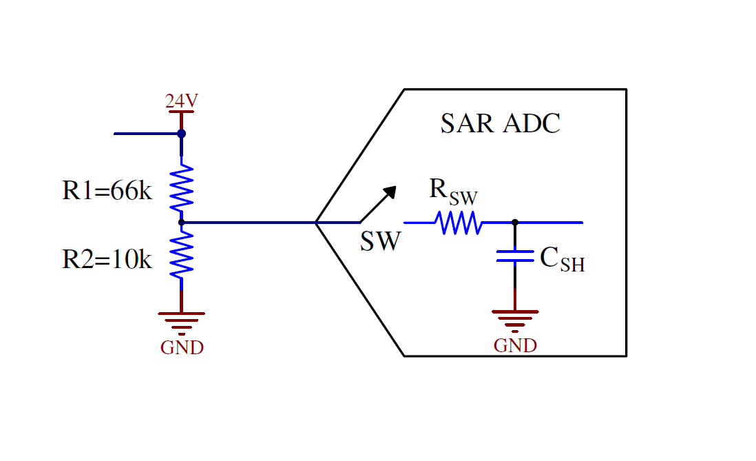
May be that in my project I'll use a voltage divider (about 66k/10k resistors) to read signals at 24 Vdc but for the moment I'm not sure...

Please, could tell me which is the limit for the impedance of the signal source that it is not necessary the use of the buffer?

Thank you, Nicola

  • Nicola,

    The reasoning behind this comment is that a SAR ADC requires the input capacitor to be charged in order to perform the rest of the conversion. If the input impedance is too high then it will take longer than a conversion time to charge the capacitor and therefore degradation in the accuracy of the conversion.

    With that in mind there isn't really any "necessary" time to include a buffer if you can tolerate the inaccuracies. Also if the signal is particularly slow moving this could be less of a concern - perhaps the first conversion would have some poor accuracy but the input capacitor would continue to charge and be accurate maybe on the second or third conversion.

    The time-constant for your circuit with 66k series resistance and 73pF input capacitance for the SAR ADC is 4.8us, so it would take 24us to charge all the way to 24V. Given the divider it would only take about 3us to charge to 3.16V. Conversion time is 2us typical. If you're reading very low frequency signals then this would probably be acceptable by the second conversion cycle. Otherwise depending on the amplitude and frequency of what you're trying to measure, it may be helpful to include the buffer between your divider circuit and the ADC inputs.
  • Hi Kevin 

    Only to understand better, here attached you can see a sketch of my output connected with the ADC. From the datasheet Csh=73 pF and the conversion time is 2us.

    When does the second conversion time start? Does it depend from many channels are working?

    Thank you.

    Nicola

  • Nicola,

    In general SAR ADCs offer two approaches for multi-channel devices; either a single ADC with a MUX or multiple ADCs. Typically if there are multiple ADCs the products are branded as "Simultaneous Sampling", otherwise most likely it is the MUX'd approach.

    AMC7812 implements the MUX-based approach so your comment is correct that the next conversion cycle depends on how many ADC channels you are using. The datasheet explains this in part with the autocycle update rate specification assuming all 16-channels are enabled as 32us.

    Keep in mind that in this case the same sampling capacitor is being used for every channel. So if the previous channel has charged the capacitor to some other value, the comments I made may not hold true. One way to help the situation would be to include some "charge well" capacitor in between your resistor divider and the ADC input. In this case the capacitor can help source some of the current to charge the input capacitor instead of the current flow being limited by the 66kOhm resistor.
  • Thank you Kevin for the support.

    In my application I should measure 16 different voltages with good precision. All the voltages come from a "voltage divider" like that of the sketch sent yesterday.

    Which is the better solution? What could you suggest me?

    Nicola

  • Nicola,

    Thank you for your patience. I was out of office for a long weekend during the Easter holiday in the US.

    What is the expected frequency of the input signals to these resistor dividers which you wish to measure? Are they near DC?

    If they're very low frequency signals It would be pretty easy to reduce the time needed to charge the sampling capacitor by including a charge well capacitor at the output of the divider. I put a simple model together very quickly and threw in 0.1uF (somewhat randomly - just a commonly available value) which seems to work pretty well. In a more comprehensive model I swept capacitor values, pretty much anything above 15nF will get you similar results to the 0.1uF, you can also go down to 8nF and not have lost too much accuracy.

  • Hi Kevin.

    My signals are very low frequency and so I'll use a capacitor at the output of the divider.

    Many thanks and best regards.

    Nicola