This thread has been locked.

If you have a related question, please click the "Ask a related question" button in the top right corner. The newly created question will be automatically linked to this question.

TPL0501-100: Why is ratiometric Temperature Coefficient big for small Codes?

Part Number: TPL0501-100

I have a question concerning digital potentiometer in general and referring specifically to the TPL0501.

See Page 7 of Datasheet

The temperature coefficient in Potentiometer mode is above Code=80 extremely good (good matching). I don't understand why the matching is getting worse, when approaching small Code-Values. I especially don't understand why the TC is getting worse for small Codes, but not for large ones. Does that have to do with the internal switch-resistor architecture?

In my application I need a ratio of around 17:1, which means, that I would have to use DAC-Codes of around 7 to 15. In this region the matching is not good. What would happen with the curve, if I connect the  "HA" Terminal to GND and the "LA" Terminal to +Vref and could therefore set the potentiometer Code to around 250? Would that help concerning TC, or would the curve change?

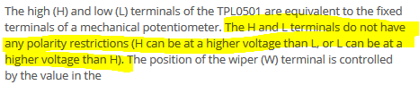
The datasheet on Page 8 states this is allowed:

  • Hi Silvan,

    To be quite honest I am not certain of the internal implementation of these devices and it will likely be difficult to track down many details given the age of the products and their associated design databases. I will see what I can dig up though.

    From the datasheet standpoint I agree that your proposal of flipping H and L and using the opposite polarity of codes is allowed. Whether this is going to maintain the same behavior in terms of drift I am less certain of since you'd also change how each switch is biased.

    Certainly something exceptional concerning the ratiometric matching is expected to happen near the rails as the datasheet elected to specify these terms with the wiper at mid-scale.
  • Hi Kevin,

    Thanks for your reply!
    Exactly, that's the question, will the behaviour be the same in terms of drift, if I change the polarity.
    I am looking forward to get some more details from you.
  • Silvan,

    I am still trying to get access to the appropriate data in order to understand this better. Some delays on account of the long Easter weekend in the US. The good news is I think I have tracked down where it is, it's just a matter of being granted access to that database.

    Hopefully I have something new for you before the end of the week.

  • Hi Silvan,

    We were able to gain access to the design database and get in touch with someone from the design team for this device. The insight I have received from them is that essentially the design is exactly symmetrical with respect to the H and L pins, so if you were to invert the two and use the higher codes you would effectively see the same drift concerns which are dominated by the switch impedances and metal resistance. From looking around at what is available industry-wide, this seems pretty typical (at least for the devices which actually publish such a curve). Even for the devices which do not publish this information, I would anticipate very similar behavior.
  • Hi Kevin,

    Thanks for your investigations and your qualified answer. Therefore if matching is really important, you should not operate the digipots near the rails.

    Thanks again.