This thread has been locked.

If you have a related question, please click the "Ask a related question" button in the top right corner. The newly created question will be automatically linked to this question.

ADS1118: latch up or memory?

Part Number: ADS1118

I´m having a kind of "latch up" or memory at ADS1118 in the circuit shown below (differential isolated) as follows:

  1. AN+,AN- =Vdif= 3.5 mV, DC at the multimeter. Test runs for about 2 hours with no problem. Vout at worst is about 200uV over real multimeter. Microcontroller sampling rate is ~58Hz.
  2. Then I start to change Vdif back and forth manually, thru a resistive divider with a potentiometer (ex: 20mV, 30mV, 10mV, 3.5mV)
  3. When I stop to change Vdif, some seconds after, Vout goes over Vdif for about 2mV. For example, multimeter shows Vdif=3.5mv but Vout=5.5mV.
  4. Even if I change Vdif= 15mV, Vout=17mV (no matter Vdif value, Vout is always ~2mV over)
  5. Even if I turn power off/on for 1 minute, it starts ok, but after some seconds it has the 2mV difference again.
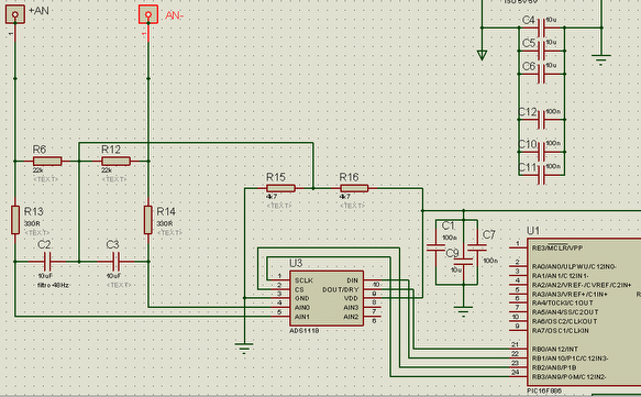
  6. The circuit is galvanic isolated from anything else, so it´s ""floating". The power supply is isolated, as well the rs485. So, the circuit is "tied" (referenced) only to AN+, AN-, and there is no way to connect ground to AN+, AN- circuit. There is no usable mid point or ground at that circuit.
  7. -----------
  8. So, I took out the C2 and C3 (48Hz filter ceramic cap.). About the sameVout/Vdif difference after some seconds
  9. Then I took out R6, R12. Same problem, but seems that Vout-Vdif =~ 1mV (in fact I took off the 2.5V to "tie" the diferential inputs at the middle of 5V power). 
  10. If I put my finger at ADS1118 VIn+ and VIn- (and maybe other surrounding pins) it "discharges", Vout goin a bit below Vdif. But few senconds later it returns to the same Vdif/Vout difference =~ 1mV
  11. I din´t the finger test when capacitors and/or R6,R12 where there.

Thanks in advance

Jose Breitinger

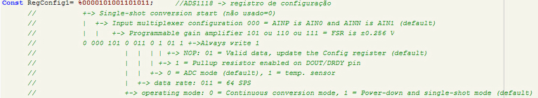
ADS1118 register settings:

  • Jose,


    Just to be clear, you establish a differential input between AN+ and AN- of some small voltage. However, this input voltage source is galvanically isolated so it is floating with respect to the ADS1118 supply?

    If this is the case, the input voltage should not be floating with respect to the ADS1118 supply. The input voltage at each input AN+ and AN- is required to be within the range of the supply for correct sampling. Allowing the inputs to float may cause sampling problems because the input voltage could drift out beyond the supplies.

    If you have a galvanic isolation and you need to measure a voltage, the measurement and the ADS1118 needs to be on one side of the isolation while the rest of the circuit with the microprocessor is on the other side.

    It's possible that I've misunderstood your explanation. If that's the case, just follow up with another post.


    Joseph Wu
  • Hi, Joseph, thanks very much for your prompt answer.

    Yes, the input voltage AN+- is floating in respect to ads1118 + microcontroller, I used a DC-DC isolator fr the 5V. The board is also conneted thru a max1480 (isolated) RS485. So, all the circuit is floating in respect to external world.

    To make AN+- not to float, I put R6/R12=22K, connected to a 2.5V "central point reference"(Vcentral). I obtained this Vcentral dividing the VDD 5V with R15/R16, 4K7 each, after a filter near ads1118 (c1,c9,c7).

    Just a reference, R13/C2 and R14/C3 are suposed antialias ~48Hz filters, connected to Vcentral point too,

    For tests, I also took off C2/C3 (10uF, smd, low esr, ceramic) as they could be laching up something. But, looking at the multimeter, Vin=3.5mV and Vout= 5.5, no matter C2/C3 where there or not. And remember that it took few seconds to reach the 2mV diference. In other words, the circuit at first works ok, only when I start to change Vin, things become wrong. Also, it worked for 2 hours  up to when I star to change AN+- diference (Vin).

    I do not have a way to connect ads1118 ground to the final circuit. In the future, it will be a current shunt, at the top of a 240V DC current, that can be hundreds of amperes. Current in the shunt could be in one or other drection (charging/discharging batteries).

    Some considerations: any multimeter is a diferential ADC, that is floating in respect the voltage it´s measuring, The diferential voltage  can be positive or negative in respect it´s probes. You can consider that this is what I need. A mutimeter, isolated from world,  that can measure voltages betwen 60mV and 10uV. 10uV =~1 Ampere at the shunt. Initial precision (fixed initial offset) is not a point. Linearity is. Also, microcontroller measures at 58 SPS, and after 5 secons =~290 samples, make an average and send 16 bits thru rs485.

    maybe?: I´m using PGA=8, => ref=250mV.  I´m using Vcentral= 2.5V. Differential Vin at maximum= 60mV. PGA amplifies the differential Vin or amplifies AN+, AN- in respect to asd1118 ground and difference is done after? Theoreticaly, if amplifies Vin dif, no problem. But if amplifies each AN+-, could be a problem this Vcentral at 2,5V. I can change Vcentral (to 250mV, for example), just changing R16/16 relationship... I din´t try that. Make any sense?

    Thanks in advance

    Jose

  • Jose,


    At first glance, I would imagine that your R6/R12/R15/16 would probably work, dragging the floating input to the input range of the ADS1118. If the input circuit you're measuring is truly isolated then you should be able do that. However, I've never done a circuit like that and I'm not sure about how to solve the problems that you're running into right now. I'd note that regardless of whether the input circuit is isolated, the input voltage for the ADS1118 must be within the ADS1118 supply. In that sense you may have an input circuit that is isolated, but it's really connect to the non-isolated supply through a resistance.

    You mention that what you really need is similar to a multimeter. In a multimeter, you either have the supply running off of a battery, which would be isolated. Or with a lab multimeter you could have the multimeter ADC running off of an isolated supply with communication across an isolation barrier to the microcontoller. This way, the resistor bridging you are doing would be easier to do.

    I'm not sure where the 2mV error that you see is coming from. I would have guessed that this is an error coming from balancing the resistor bridging at the front end of the ADC, as the currents are imbalanced as the isolated and non-isolated supplies are set to some common point. However I would have expected errors to settle as the supplies converged.

    The ADS1118 sampling works by sampling the voltage between AINP and AINN (not by individually sampling AINP to ground and AINN to ground and then subtracting). This definitely helps get a good reading. However, if AINP or AINN isn't within the supply range, the sampled charge bleeds out of the sampling capacitor into VDD or GND. You can try to play with the gain, or the Vcentral point, or even change the resistances and capacitances. I'm just not sure what will help best.


    Joseph Wu
  • Jose,

    If the input voltage is small and isolated, then you might treat it similar to how you would treat a thermocouple. You could attach a large resistance (~500kΩ) from AN+ to VDD and another same large resistance from AIN- to GND. Then remove the remaining resistors on the front end. You would have something like this in the end:

    The two matched resistors balance the input at the front end without loading the source voltage. I would check to see if this works and gets you results without any kind of settling with changes in voltage.

    Joseph Wu

  • Hi Joseph, thanks again for all your effort.

    You are right, all the isolations I did for the PCB ( ads1118 + MCU + rs485), iintended to be like it was operated on batteries like any ordinary handhel multimeter.

    I never tested with real batteries, but the idea is that. The DC-DC power supply isolator is NXJ1S0505MC (5V-> 5V). And the rs485 driver+isolator is MAX1480.

    So, If we use the same tecnique that any handheld multimeter does, I shoud work.

    Your above  idea (500M resistors) sounds to be very intresting.....As you told, I will eliminate the 22K (or 44K) input impedance.  If nothing come on before Friday, I will test it.  :-((.

    But as it cuts the antialias filter could I run in the alias problem?

    a question:  I suppose ads1118 could be used to do a plain hand held voltimeter (a multimeter just for voltage), correct?    If yes, how to handle the diferential voltage that is not referenced to the multimeter? Probably as per your suggestion above. 

    Or, do you have na idea on how multimeter producers  normally handle their reference? 

    Jose

  • Jose,

    Using the resistors for biasing doesn't mean that you can't use an anti-aliasing filter on the front end. You can still use one like this:

    The ADS1118EVM uses the same type of front end.

    As for your other comments, generally, I've worked on different temperature circuits. I've never worked on a multimeter type circuit so I don't have much detailed information about it.

    Joseph Wu

  • Joseph

    Thanks, I think next step would be to test your suggestion above. Conceitually I understand and agree,  and also it is used in practice at  ADS1118EVM .

    As I´m new at this fórum and as only at Friday I will be able to check, it´s the moment to close this tread? Or is  better to wait up to the tests?

    Thank you very much, you help was very crutial.

    Jose Breitinger

  • Joseph

    After some days testing the above circuit, as many ways I could imagine with a precision voltaage source calibraated in uV, it´s working perfectly and ADS1118 has a very high initial precision and linearity . For the filter, resistors are 330 Ohms and C is a 10uF smd, ceramic multilaayer.

    Thanks again

    Jose

    *

  • Jose,


    I'm glad you were able to find a good solution. I was hoping the sensor/ADC connection that I suggested would work for you.

    Regardless, if you have further questions, or follow-up questions, please feel free to post again (either attach it to this post if applicable, or start a new post).


    Joseph Wu