This thread has been locked.

If you have a related question, please click the "Ask a related question" button in the top right corner. The newly created question will be automatically linked to this question.

WEBENCH® Tools/TSW1400EVM: TSW1400EVM

Part Number: TSW1400EVM

Tool/software: WEBENCH® Design Tools

Dear TI expert:

     I am investigating TSW1400 for ADC (ADS4449 EVM)data capture.

    TSW1400 is now linked to the HSDC .

    When I select ADS4449 in the upper left corner of the HSDC panel, I am prompted to download the firmware. “Do you want to update the Firmware for ADC” .I chosed"Yes."    At this point, another dialog prompt    did not find the firmware.

Question1 : where can I find the firmware of the TSW1400 corresponding to ADS4449 ?

     If I press down the  SW6 of TSW1400 EVM at the same time when update the firmware,it is OK.

Question 2.Is this the right way to operate?

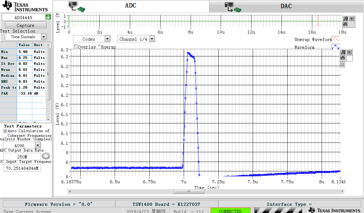
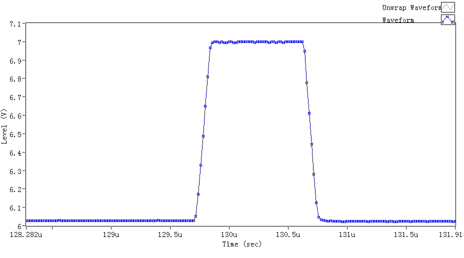
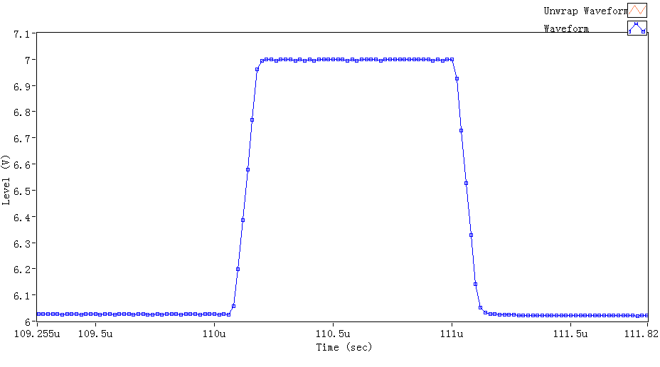
     I sample the J10 40MHz 1.5Vpp sine clock for ADS4449 EVM, and then give the ADS4449 EVM's J6 10MHz 1.0Vpp sine wave.

When I click the capture button, an Error reported in the attached picture.

So, what's going on here?

  • Guoming,

    Make sure the 5V power supply to the TSW1400EVM is capable of providing at least 4A. After you clicked on capture, what was the status of LED's D1-D9?

    Regards,

    Jim 

  • Jim,

    Thank you very much for your reply.
    As you said, I've changed the power current.
    If I press down the SW6(CPU_RESET)of TSW1400 EVM at the same time when update the firmware,These LED will be lit up:D1、D2、D3、D4、D7、D8、D9.
    If I click on the capture button, all these LED don't respond.
    Is this the right way to download firmware?Because I didn't find the firmware for ADS4449, I just pressed down the SW6(CPU_RESET) of TSW1400 EVM at the same time when update the firmware,and the software panel of HSDC had no error dialog box.
  • Guoming,

    What version of HSDC Pro are you using? What revision is the TSW1400EVM? You should not have to hold down SW6. There may be an issue with the EVM. Can you try to download a DAC firmware without pressing this reset switch?

    Regards,

    Jim

  • Jim,

    Thank you again  for your reply.

    A good news ,The problem has been resolved. Both  TSW1400 and ADS4449 are working .

    The cause of the problem is power supply. As you said Make sure the 5V power supply to the TSW1400EVM is capable of providing at least 4A.

    But I still have to press down the SW6(CPU_RESET)of TSW1400 EVM at the same time when update the firmware. Although I haven't found the firmware for ADS4449.

    Here's a picture I intercepted. There's a new problem. The amplitude of the pulse signal is 1V .The starting point of the pulse signal is 0V. Why is the capture starting at 6V?

    Frequency of sampling & Pulsing signal  :

    The version:TSW1400 REV D,ADS4449 REV E .

  • Guoming,

    Did you modify the input stage of the board or is still connected to the transformer and AC caps? If you do a capture and look at the codes as a digital number instead of a voltage, this may help explain what you are seeing. Try sending a simple low frequency sinewave with a known amplitude and see how this correlates to the captured results.

    Regards,

    Jim

  • Jim

         I didn't modify the input stage of the board. I just connected the input  to the transformer and AC caps.

    I captured the data again today,but the waveform still started at 6V. In addition, it attenuates to a fifth of the time.

    Here's the chart.  The true input signal amplitude is 1 Vpp. start at: 0V. But the result of the capture is 0.2Vpp,and start at 6V. So why?


  • Guoming,

    Using the ADC GUI, write to register 25h and set the ADC into digital ramp mode. Set the TSW1400EVM to do a capture and display in codes mode. You should now see a ramp. If you do not, the problem may be with the TSW1400 board. If you do see a uniform ramp, we can focus on the ADC board.

    Regards,

    Jim   

  • Jim

         I could see a uniform ramp ,as follows:

         a uniform ramp:

    ALL  Zeros:

     So maybe there's something wrong with the ADC board?

  • Jim
    I just measured the ADC board with an oscilloscope.
    I found that the attenuation of the signal occurred on the ADC board.
    For example:
    If the amplitude of the input signal (output by signal generator) is 1V, the differential voltage after transformer and AC caps is just about 0.25V.
    (I measured the voltage between R17 and R28 on the ADC board.)
    This explains why the signal attenuated to a fifth of the time after ADC acquisition.
    I still don't know why the signal started at 6V. I thought the common-mode voltage was incorrect.
    The common-mode voltage which is 1.15V is very stable after the sampling frequency signal is given.

    Can you tell me why there's a 6V bias?
    Why the voltage after transformer and AC caps attenuated to a fifth of the time. Is the ratio of the transformer 1:1 ?


    Best wishes
  • Guoming,

    This board has back-to-back transformers and a filter on the analog input. This is what is causing the attenuation. Please change the Y-scale to codes on HSDC Pro when capturing data. You will see that the output is centered about midscale of the device. The voltage scale shows this to be about 6V. This voltage scale is not a 1:1 correlation with respect to the input voltage so I suggest you do not use this to avoid any confusion. If you need to send in a true differential signal with no loss, you can bypass the transformers and remove the filter stage. Just make sure to either leave the VCM circuit in place with the AC coupling caps or guarantee the input on both legs swings about the common mode voltage (1.15V +/ 25mV ) of the part.

    Regards,

    Jim 

  • Jim

       AS you said in your letter.

       I  changed the Y-scale to codes on HSDC Pro when capturing data.

    But the waveform I captured is still biased,As shown below.

    The initial waveform is actually an amplitude of 1.4 V


    The amplitude of the  initial waveform is actually 1.4 V from 0V.  Is something wrong with HSDC?

    The problem haunted me for a long time, hoping to be solved as soon as possible.

    In addition, ADS4449, according to the sample codes. how to calculate the original voltage?


         Good luck           

                                                                              Guoming Sun


  • Jim

           There's a new problem.

           When the input pulse amplitude exceeds 1 V, the waveforms displayed by HSDC Pro no longer increase in value.  As shown below:The first image is a Vpp=1.5V waveform,the peak is 7 V.

    The second image is a Vpp=1.2V,but the peak is still 7V.   why?  

        The differential input  voltage is 1.15V . The allowable input voltage value of ADS4449 is -0.3V--1.9V,When the pulse amplitude is 1.5 V,The forward end of differential voltage is about  750mV+1.15V=1.9V(I Used THS4503 EVM to transform single end signal into differential signal,then connected to the differential input pin of the ADS4449).

        So why the HSDC  Pro didn‘t  show a higher amplitude when the voltage of the pulse over  1 V ?

  • Guoming,

    If you switch the Y-axis to codes, you will probably see that the ADC has reached it's max output value and is now in saturation. What is the P-P voltage across the analog input pins when this occurs? I am guessing it is above the max for the device. Since you are using the THS4503 EVM to convert your signal, I am guessing you are also getting some gain from this device which may be the reason for the saturation. What is the state of the over range pins? More info regarding these outputs can be found in section 8.3.1 of the data sheet. If the device is not in over range, then the issue is probably the common voltage on the input is not set properly.

    Regards,

    Jim 

  • Guoming,

    Is it possible to send a oscilloscope screen shot with a differential scope probe connected across both inputs of this channel? Can you change the input to simple 1MHz sinewave and send me the HSDC Pro screen shot?

    Regards,

    Jim