This thread has been locked.

If you have a related question, please click the "Ask a related question" button in the top right corner. The newly created question will be automatically linked to this question.

ADS8691: Device configuration and register maps

Part Number: ADS8691

Hi all, 

Could someone explain to me what actually happens when I program the register. 

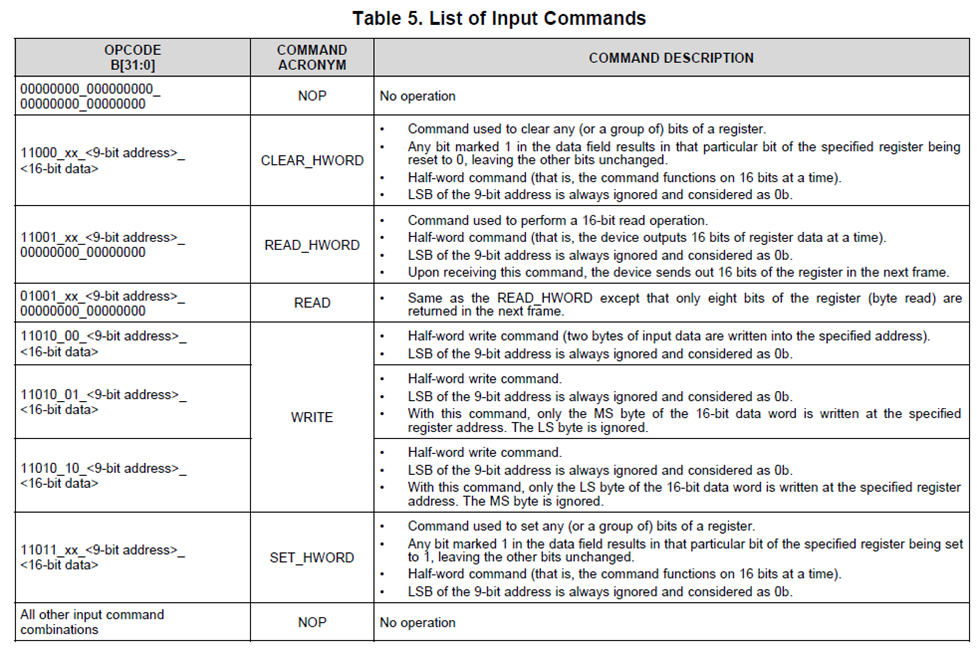
for example in this datasheet: www.ti.com/lit/ds/symlink/ads8691.pdf 

Is the 0x02 referring to the Address for bits 23-16 = 02h or is it putting 0x02= 0010 in to the 32-bit integer making it 0000 0000 0000 0000 0000 0000 0010

The thing is for this example the device addres is set and should be read from the 16-19 bit making it 0000 0000 0000 0010 0000 0000 0000 which is 2000h in HEX

Hope someone gets my confusion and can help.

Best regards,

Dukel

  • Hello,

    Thanks for your query on E2E, I will get back to you soon.

    Best regards

    Dale

  • Hi Dale,

    Could you find an answer to my question?

    Best regards
  • Hello Dukel,

    I apologized for late response. The 02h is the address for bits 23-16 of register.

    Here is an example to use READ_HWORD command to read the 16-bit content of ALARM_H_TH_REG register:

    (Byte 0 Address for bits 7-0 = 24h, Byte 1 Address for bits 15-8 = 25h, Byte 2 Address for bits 23-16 = 26h, Byte 3 Address for bits 31-24 = 27h)

    1. Read_HWORD command reads the 16-bit (0~15 bit) of register:               Data frame:       <11001_xx> <0_0010_0100><00000000><00000000>
    2. Read_HWORD command reads the 16-bit (16~31 bit) of register:             Data frame:       <11001_xx> <0_0010_0110><00000000><00000000>

    Please pay attention to below information:

    1. A “0” should be added prior to the address to have a 9-bit address: 0_0010_0100b for address 24h.
    2. LSB of the 9-bit address is always ignored and considered as 0b.
    • To write/read both byte 0 and byte 1(or byte 2 and byte 3) in one command, the low byte address (byte 0 or 2) should be used. If the address of byte 1 or 3 is given, the LSB (bit 0) will be ignored, because it is a 16 bit address now.
    • HWORD commands can only write to the addresses of byte 0+byte 1 or byte 2+byte 3 and so on. They cannot write to byte 1+ byte 2.

    Please let me know if you have any other question. Thanks.

    Best regards

    Dale

  • Thank you for your reply.

    But for example when I put the following line in my program:
    #define RANGE_SEL_REG       0x14 // Input range selection control register

    The address I'm writing to is 0x14 (14h) and lets say I want to enable the internal reference and take ±2.5*Vref. Do I first write the 0x14 (10100) and after that the 32 bit of 0000 0000 0000 0001 where the 6th bit is 0 to enable internal reference and bits 3-0 are 1 to choose ±2.5Vref
    Bit:   31-16 15-8   7-4   3-0

  • Hi,

    The address should be combined with Write command and your data together to create a 32-bit OPCODE, please refer to the table as below:

    Best regards

    Dale

  • So the variable that I send should be: 11010_00_000010100_0000000000000001 if I want to Write towards RANGE_SEL_REG the value 0001b = ±2.5 × VREF that is specified in the datasheet. This converted to HEX is: D0140001

    Thanks again for your reply Dale!
  • Hi Dukel,

    That's correct, thank you for selecting TI precision ADCs.

    Best regards

    Dale