This thread has been locked.

If you have a related question, please click the "Ask a related question" button in the top right corner. The newly created question will be automatically linked to this question.

ADS1262: Why do I get a wrong conversion result?

Part Number: ADS1262

Hello,

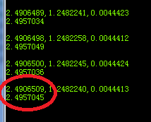
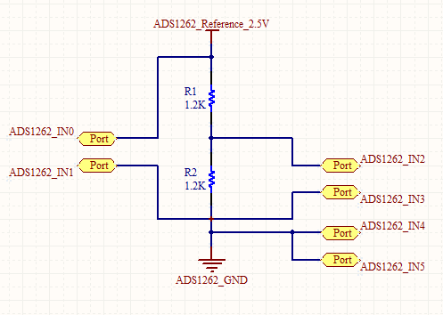
I sample a differential voltage using the ADS1262(AIN0-1),I short the two channels and ground,But the voltage I get is not close to zero(About 3.67mv).And,I divided the reference voltage in half and then sampled,the result is 1.237V(The voltmeter value is 1.246V).

I use the pulse mode,here my code:

SPI_SendByte(ADS1262_CMD_START);
ADS_CS_LOW();
while(ADS_DRDY); 
SPI_SendByte(ADS1262_CMD_RDATA);

for(i=0;i<5;i++)
ADC_Bytes[i] = SPI_SendByte(0);

sum = (ADC_Bytes[1] << 24) | //Data MSB
(ADC_Bytes[2] << 16) |
(ADC_Bytes[3] << 8) |
(ADC_Bytes[4] << 0); //Data LSB

My output data field is 5 bytes long,first is STATUS.

The converted voltage value is obtained by the following code:

Voltage_x=(double)Result_x*2.5/(double)2^31;

  • Hi Guanzhong,

    Is AVSS connected to -2.5V or GND?

    If AVSS = GND and you are shorting the inputs to ground then you may have a problem since the internal PGA outputs cannot drive all the way to 0V. Therefore, you might be operating outside of the linear range of the PGA. Try shorting you inputs to a mid-supply voltage, such as 2.5V and see if you get a result that is much closer to 0V.

    Also, you might need to make sure that the /CS pin is set low in your code before you send the SPI START command.

    Best regards,
    Chris
  • Hi Chris,

    Thank you for your answer!

    I'm using the ADS1262 to read three load cells (AIN0-1, AIN2-3,AIN4-5)

    I'm using the pulse conversion mode, 50sps, changing the input multiplexer register (AIN0-1), sending the "START1" command, waiting for DRDY go low, reading, sending the "STOP1" command, changing the input multiplexer register (AIN2-3) and repeating .

    My problem is that the value obtained from multiple channels is not the same as the value obtained from a single channel.

    Above is that I use of multiple channels AIN0-1(AIN0-1, AIN2-3,AIN4-5).The bottom is that I use a single channel.

    Looking forward to hear from you!

    Thanks and regards,

    guanzhong Wang

  • Hi Guanzhong,

    Would you be able to share a schematic of your circuit?

    It's hard to say what might be the issue without more data. Are the conversion results stable if you take multiple conversions on the same channel? Have you verified that the input signal is indeed constant and not changing.

    You'll also need to make sure that the reference voltage is stable. What is your reference voltage source and is this source also used to excite the load cell?

    I would trying measuring each input multiple times to see if you are getting a consistent result or if perhaps there is an RC charging effect when switching between channel. In that case you might need to try increasing the programmable delay to allow for additional settling time.

    Best regards,
    Chris

  • Hi Chris,

    Thank you for your answer and I am sorry to reply you so late!

    It is useful to  increase the programmable delay ,But I feel that this solution does not really solve my problem.

    I use the ADS1262 evaluation kit and its internal 2.5V reference source,and the microcontroller I use is STM32(SPI communication),here is my test circuit:

    When I use the single channel(IN0-IN1), I measured the voltage of 2.49698V(Any sample rate). I take multiple conversions on the same channel (IN0-IN1,IN0-IN1,IN0-IN1),the measurement result is unchanged.

    When I convert the channel(IN0-IN1,IN2-IN3,IN4-IN5) ,I measured the voltage of 2.49680V(2.5 sps,IN0-IN1),but measured the voltage of 2.49565V(50sps).

    Looking forward to hear from you!

    Thanks and regards,

    guanzhong Wang

  • Hi Guanzhong,

    Not a problem.

    Are you using the ADS1262's PGA or it is bypassed to allow for a wider common-mode input range?

    If you are bypassing the PGA, yes, it will allow you to measure a single-ended input referenced to ground; however, because your resistors are not a low-impedance source, you might have some gain error resulting from measuring the voltage divider directly into the ADC's modulator (which is not a high-impedance input).

    I would recommend retrying the measurement with a low-output impedance source, such as a bench supply if you have one available.

    Best regards,
    Chris