This thread has been locked.

If you have a related question, please click the "Ask a related question" button in the top right corner. The newly created question will be automatically linked to this question.

ADS5527: differential input signal configuration

Part Number: ADS5527


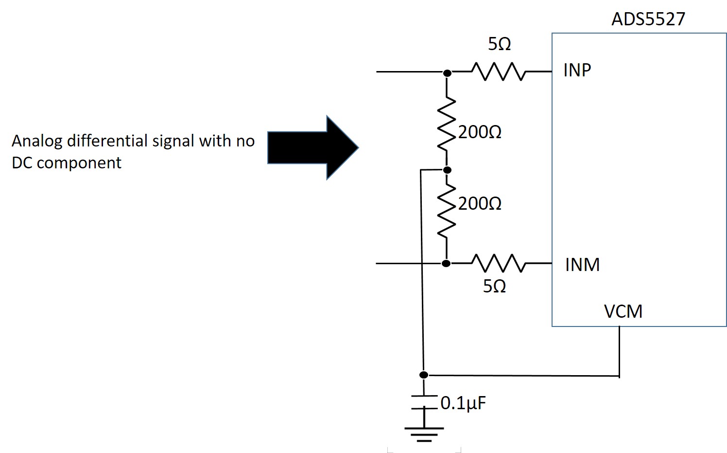
I'm designing a board that integrate an ADS5527. At the input I've an analog differential signal with no DC component. Looking at the datasheet of the ADCi t seems that the DC component can be provided by the VCM pin of the ADS5527. For this reason I'm using an input configuration very similar to the one shown in fig.43 of the datasheet. I've attached an image showing the driving circuit I'm using, do you think that it is appropriate for good operation?

  • Hi Dan,

    We are looking at your question and will get back to you soon.

    Regards,
    Neeraj
  • Dan,

    Why are using 200 Ohm resistors in your circuit? Normally, we have the input trace impedance set to 100 Ohm differential and would terminate using two 49,9 Ohm resistors instead. Otherwise, as long as the signal on each analog input leg swings no more than 1V-PP centered around 1.5V (VCM), this should be ok.

    Regards,

    Jim 

  • Dear all,

     thanks for the reply. 

    I have a few remarks:

    1. The schematic we're using is extracted from the data sheet (Fig. 43). Why you say that it would be necessary to use 100 Ohm resistors?

    2. More in general, the problem we have is to set the analog input circuit of the ADC. 

         2a. What happens if we do not use any resistor and we do not use any bias in input? We've done some tests and the ADC seems to be still sampling properly. Is it correct? Is there any limit (minimum signal amplitude) in input? Please consider that we have to test the circuit just using a sin wave (less than 100 MHz). We have to be able to sample only this simple signal which we expect to have a differential amplitude of tens of millivolts. 

         2b. Can you please clarify me what is the correct configuration of the input circuit in case I'll use a biased differential signal? For instance, in Fig. 40 there are 2 33 Ohm resistors instead of the 200 Ohm ones.

  • Can anybody answer my last question?
  • Emilio,

    Based on your question 2, we cannot fully understand what you are trying to do. Can you send a schematic drawing of exactly what you plan on using including the signal source? 

    Regards,

    Jim


  • Dear Jim,

    At pag. 32 of the datasheet I read  "The INP and INM pins have to be externally biased around a common-mode voltage of 1.5 V available on VCM

    pin 13."

    For me It is not clear how to bias the INP and INM pins using the VCM pin. 

    In the attached image you can see a possible solution, however we are not sure that this is the best solution. If yes please suggest the value of Rx to be used. Otherwise, if you have a better solution, could you provide a schematics showing the connection of VCM to the input?

  • Emilio,

    If you are not using AC caps, you need to make sure there is no DC component on the input sources. Otherwise, the VCM pin will not be able to set the two inputs to the correct CM voltage level. Assuming you are using internal reference mode, what you show should work as long as both signals are exactly the inverse of the other and they do not exceed 1V P-P amplitude. You can use 200 Ohms for the resistors.

    Regards,

    Jim

  • Dear Jim,

    thank you for the useful information.

    I've a last question .

    I've inserted the modification that you have suggested (DC blocking capacitors and 200ohm resistance) in the attached figure (see configuration 'A'). Could you confirm that this configuration should work?

    In the same figure I've also shown another configuration (called configuration 'B'). Do you think that configuration 'B' does not work properly? Maybe it could work with some noise problem?

    Regards,

    Emilio

  • Emilio,

    "A" will work, but "B" will not as the input on each leg will be centered around 0V. These need to be centered around 1.5V.

    Regards,

    Jim