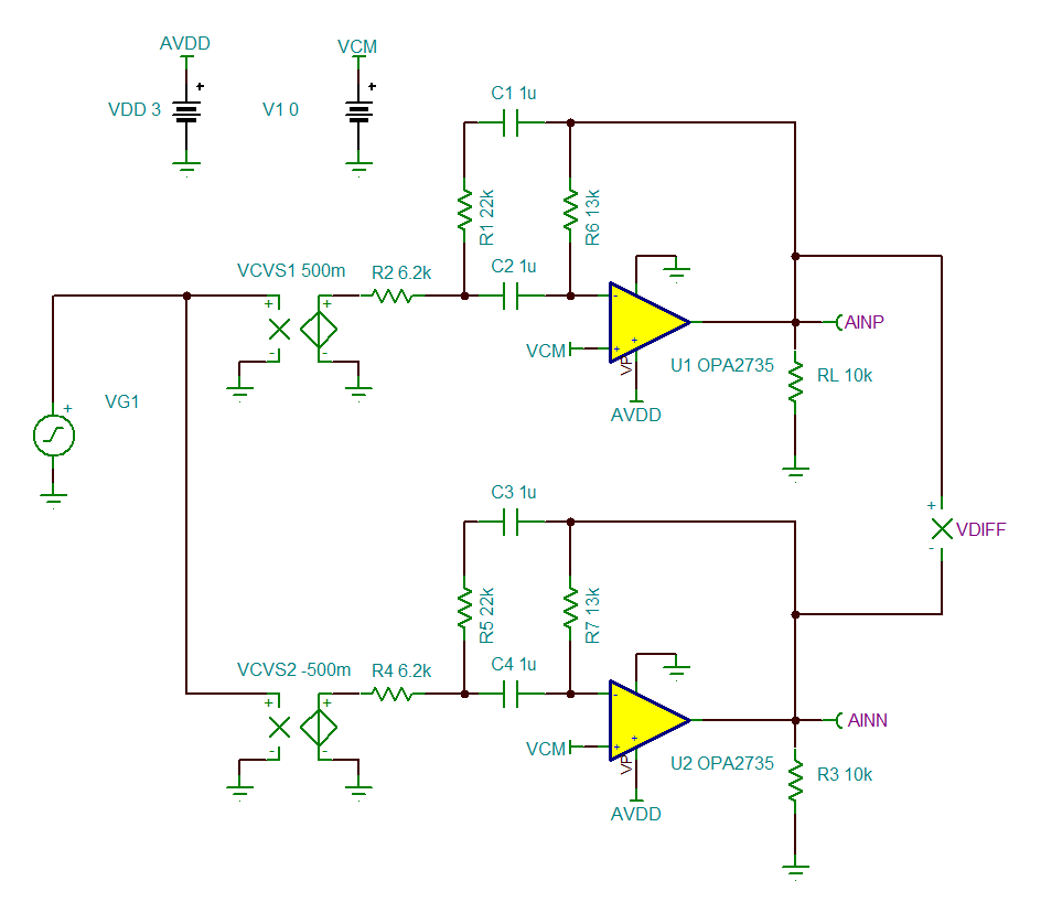
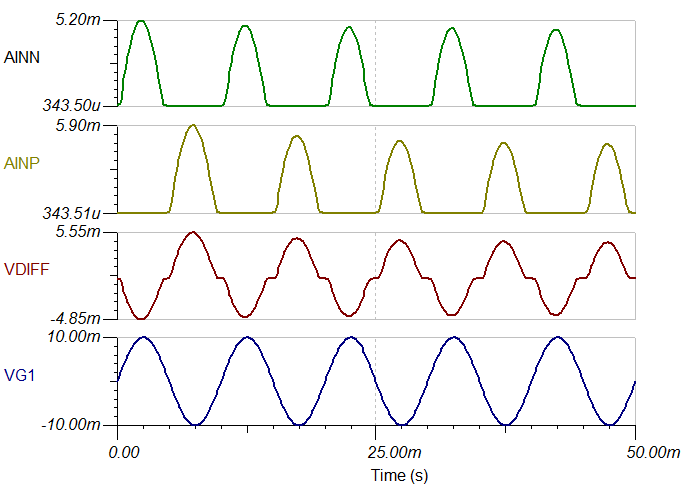
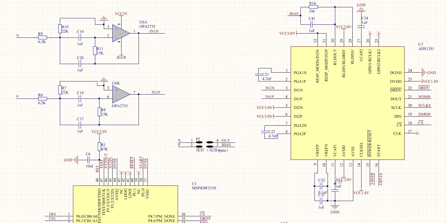
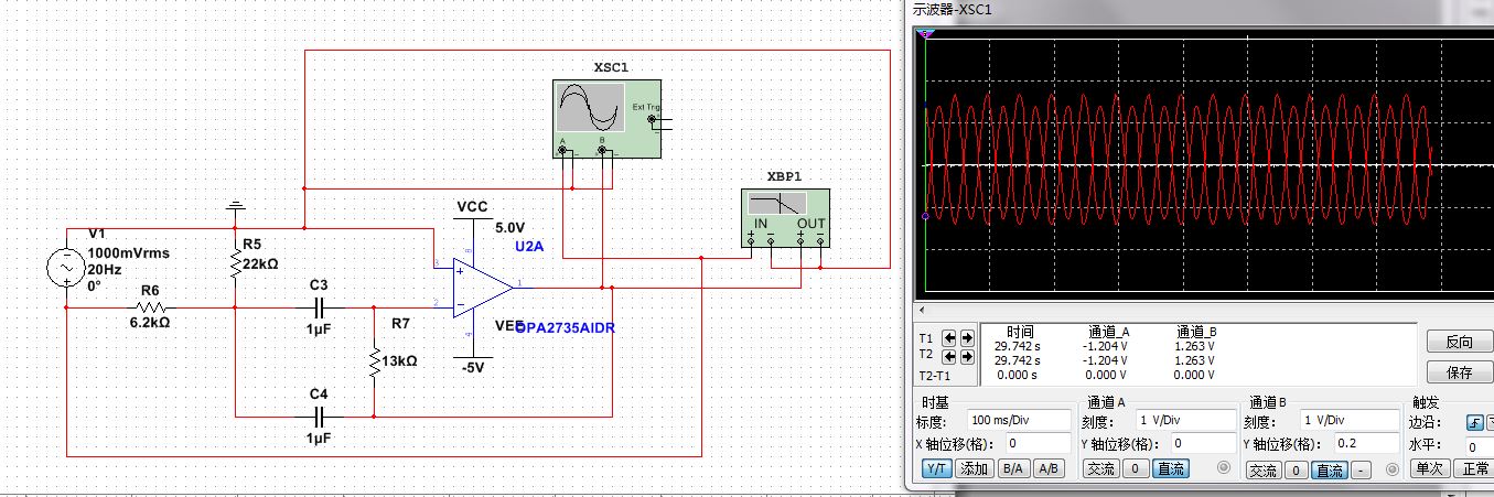
i know ADS1292 is designed for ECG acquisition,but i want use it to acquire EEG signal,could this be realized?and i have designed a circuit for this ,but i don't know Whether it right or not。
This thread has been locked.
If you have a related question, please click the "Ask a related question" button in the top right corner. The newly created question will be automatically linked to this question.
i have uploaded the schematic ,and i use Differential Input,before the Differential Input is Band Pass Filter. and hope you give me some advice?thank you!
Hello,
Thanks for posting the schematic. Here are a few things I noticed:
The simulation below shows the output signals for VIN = 10 mVp sine wave at 100 Hz. The clipping disappears if you increase the voltage at the non-inverting inputs by changing VCM to 500 mV. However, keep in mind that the differential offset voltage between the electrodes can reach as high as 300 mV. Therefore, you must increase the common-mode even further.
At the same time, the input common-mode voltage to the ADS1292 PGA must be at least 1.1 V, assuming Gain = 6 and max input of 300 mV. Setting the VCM on the OPA2735 to 1.25 V seems to satisfy both conditions.
It would be easier for your design if you chose either a different amplifier or a larger supply voltage such that the design could support a mid-supply common-mode. In that case, the RLD output could be connected to the non-inverting inputs of the OPA2735 and you would not need to generate a separate 1.25-V VCM. I would recommend increasing AVDD to 3.3 V. The RLD output would be centered around mid-supply = 1.65 V and could be connected to the OPA2735 non-inverting inputs.
VIN = 10 mVp, VCM = GND, AVDD = 3 V
VIN = 300 mVp, VCM = 1.65 V, AVDD = 3.3 V
Best Regards,
Thanks ! This would takes me few days to understand. But i found if the band-pass filter use bipolar supplies, and the fo of the band-pass filter approach to 20HZ,we can see that the input signal and the output signal is normal . I have change the circuit , and can the circuit work properly?
Best wishes!
Hello,
Yes, bipolar supplies will work fine with a common-mode voltage of 0 V. The goal is to keep the VCM < VCC - 1.5 V. I would recommend using +/- 2.5 V so that the same supplies can be used for the ADS1292 (AVDD = +2.5 V, AVSS = -2.5 V).
Please see attached simulation below:
Best Regards,
Thank you very much, your advice has given me great help.I have the last question,i'm not sure how N,P and Bias connect with brain . i think N and P is connected to the target section , and Bias is GND which connected far away from the target section .
best wishes!