

Other Parts Discussed in Thread: ADS1298, ADS1294, ADS1296, ADS1299
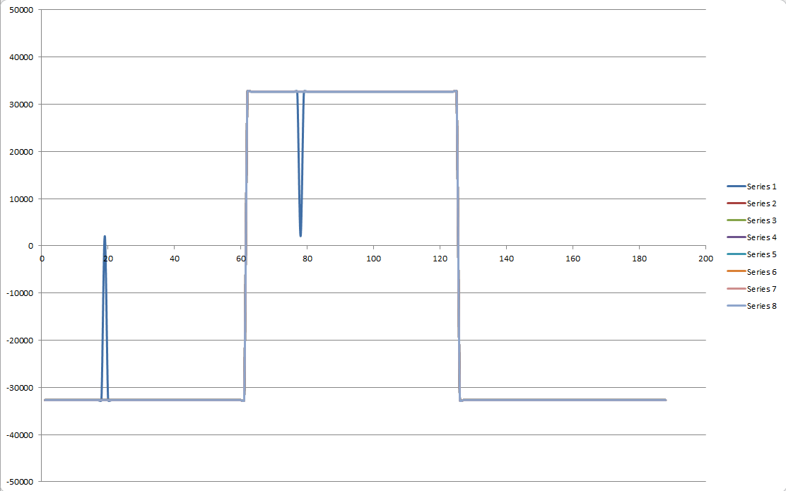
I got 8 channel test signal from ADS1198 in matlab and below is the pic of these.
Chan1 and Chan8 donot seems good Now please tell me the sol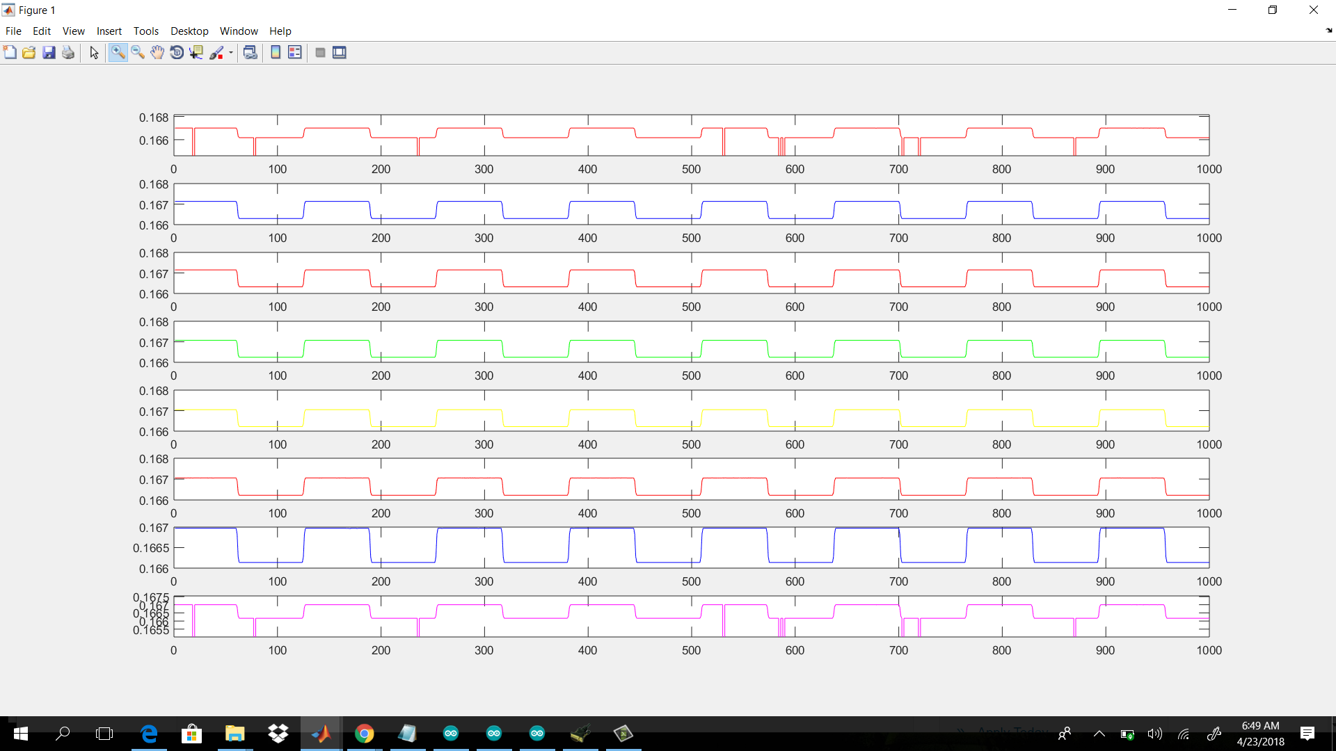
 ution.

This thread has been locked.
If you have a related question, please click the "Ask a related question" button in the top right corner. The newly created question will be automatically linked to this question.


I am working on ECG related project using TI ADS1198 and arduino DUE, i correctly read and write all the register and get ID. Now i want to get internally generated test signal, the signal that i get seems correct except for channel 1 and channel 8.
I use uni-polar supplies AVDD =3v and AVSS=1.8v
i read data in text file and then plot using Matlab
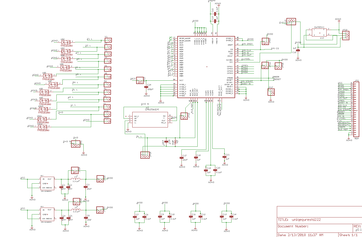
here is my complete schematic diagram
Arduino main code for getting 8 channel test signal
// Minimal sketch for connection to ADS129n family. Load this script and open Tools/SerialMonitor.
// You should see text like this
// Device Type (ID Control Register): 62 Channels: 8
// If you see "Channels: 0" then check your wiring
#include "ads1298.h"
#include "adsCMD.h"
#include "Base64.h"
#include <SPI.h> // include the SPI library:
int gMaxChan = 0; //maximum number of channels supported by ads129n = 4,6,8
int gIDval = 0; //Device ID : lower 5 bits of ID Control Register
int activeSerialPort = 0; //data will be sent to serial port that last sent commands. E.G. bluetooth or USB port
const int kPIN_LED = 13;//pin with in-built light - typically 13, 11 for Teensy 2.0.
int numActiveChannels = 0;
boolean gActiveChan[9]; // reports whether channels 1..9 are active
boolean isRdatac = false;
boolean base64Mode = false;
int sampleCount=0;
boolean isLimit=false;
char hexDigits[] = "0123456789ABCDEF";
uint8_t serialBytes[200];
char sampleBuffer[1000];
uint8_t chan1[2];
const char *hardwareType = "unknown";
const char *boardName = "HackEEG";
const char *makerName = "Hamid, Mujahid, Abdul Hameed";
const char *driverVersion = "ADS1298 driver v0.1";
#if defined(__SAM3X8E__)
#define isDUE //Detect Arduino Due
//#define WiredSerial SerialUSB //Use Due's Native port
//#define NSerial SerialUSB
#define NSerial Serial1
#define WiredSerial Serial
#else
#define WiredSerial Serial
#endif
void setup(){
using namespace ADS1298;
//prepare pins to be outputs or inputs
//pinMode(PIN_SCLK, OUTPUT); //optional - SPI library will do this for us
//pinMode(PIN_DIN, OUTPUT); //optional - SPI library will do this for us
//pinMode(PIN_DOUT, INPUT); //optional - SPI library will do this for us
pinMode(IPIN_CS, OUTPUT);
pinMode(PIN_START, OUTPUT);
pinMode(IPIN_DRDY, INPUT);
pinMode(PIN_CLKSEL, OUTPUT);// *optional
pinMode(IPIN_RESET, OUTPUT);// *optional
pinMode(IPIN_PWDN, OUTPUT);// *optional
digitalWrite(PIN_CLKSEL, HIGH); // External clock
//start Serial Peripheral Interface
SPI.begin();
SPI.setBitOrder(MSBFIRST);
#ifndef isDUE
SPI.setClockDivider(SPI_CLOCK_DIV4); //forum.pjrc.com/.../1156-Teensy-3-SPI-Basic-Clock-Questions
#endif
SPI.setDataMode(SPI_MODE1);
//Start ADS1298
delay(500); //wait for the ads129n to be ready - it can take a while to charge caps
digitalWrite(PIN_CLKSEL, HIGH); // External clock
delay(10); // wait for oscillator to wake up
delay(1);
digitalWrite(IPIN_PWDN, HIGH); // *optional - turn off power down mode
digitalWrite(IPIN_RESET, HIGH);
delay(1000);// *optional
digitalWrite(IPIN_RESET, LOW);
delay(1);// *optional
digitalWrite(IPIN_RESET, HIGH);
delay(1500); // *optional Wait for 18 tCLKs AKA 9 microseconds, we use 1 millisecond
adc_send_command(SDATAC); // Send SDATAC Command (Stop Read Data Continuously mode)
// delayMicroseconds(2);
delay(100);
// Determine model number and number of channels available
gIDval = adc_rreg(ID); //lower 5 bits of register 0 reveal chip type
switch (gIDval & B00011111 ) { //least significant bits reports channels
case B10000: //16
hardwareType = "ADS1294";
gMaxChan = 4; //ads1294
break;
case B10001: //17
hardwareType = "ADS1296";
gMaxChan = 6; //ads1296
break;
case B10010: //18
hardwareType = "ADS1298";
gMaxChan = 8; //ads1298
break;
case B11110: //30
hardwareType = "ADS1299";
gMaxChan = 8; //ads1299
break;
case B10110: //22
hardwareType = "ADS1198";
gMaxChan = 8; //ads1198
break;
default:
gMaxChan = 0;
}
//start serial port
NSerial.begin(115200);
WiredSerial.begin(115200); //use native port on Due
while (WiredSerial.read() >= 0) {} //forum.arduino.cc/index.php
//while (!WiredSerial) ; //required by Leonardo arduino.cc/.../IfSerial (ads129n requires 3.3v signals, Leonardo is 5v)
delay(200); // Catch Due reset problem
pinMode(kPIN_LED, OUTPUT);
WiredSerial.print("Device Type (ID Control Register): "); WiredSerial.print(gIDval); WiredSerial.print(" Device Name: "); WiredSerial.print(hardwareType); WiredSerial.print(" Channels: "); WiredSerial.println(gMaxChan);
digitalWrite(kPIN_LED, LOW); // turn the LED on (HIGH is the voltage level)
detectActiveChannels();
WiredSerial.print("Number of active channels: ");
WiredSerial.println(numActiveChannels);
adc_wreg(GPIO, 0);
adc_wreg(CONFIG3,PD_REFBUF | CONFIG3_const);
//FOR RLD: Power up the internal reference and wait for it to settle
//adc_wreg(CONFIG3, RLDREF_INT | PD_RLD | PD_REFBUF | VREF_4V | CONFIG3_const);
//delay(150);
//adc_wreg(RLD_SENSP, 0x01); // only use channel IN1P and IN1N
//adc_wreg(RLD_SENSN, 0x01); // for the RLD Measurement
// Serial.println(HIGH_RES_500_SPS);
adc_wreg(CONFIG1,HIGH_RES_500_SPS);
adc_wreg(CONFIG2, INT_TEST); // generate internal test signals
// Set the first two channels to input signal
// Set the first two channels to input signal
for (int i = 1; i <= 8; ++i) {
//adc_wreg(CHnSET + i, ELECTRODE_INPUT | GAIN_6X); //report this channel with x12 gain
//adc_wreg(CHnSET + i, ELECTRODE_INPUT | GAIN_1X); //report this channel with x12 gain
adc_wreg(CHnSET + i, TEST_SIGNAL | GAIN_6X); //create square wave
//adc_wreg(CHnSET + i, 0x65);
//adc_wreg(CHnSET + i,SHORTED); //disable this channel
}
/* for (int i = 2; i <= 2; ++i) {
//adc_wreg(CHnSET + i, ELECTRODE_INPUT | GAIN_1X); //report this channel with x12 gain
//adc_wreg(CHnSET + i, ELECTRODE_INPUT | GAIN_12X); //report this channel with x12 gain
adc_wreg(CHnSET + i, TEST_SIGNAL | GAIN_12X); //create square wave
//adc_wreg(CHnSET + i,SHORTED); //disable this channel
}
for (int i = 3; i <= 6; ++i) {
//adc_wreg(CHnSET + i, SHORTED); //disable this channel
adc_wreg(CHnSET + i, ELECTRODE_INPUT | GAIN_12X); //report this channel with x12 gain
}
for (int i = 7; i <= 8; ++i) {
adc_wreg(CHnSET + i, ELECTRODE_INPUT | GAIN_1X); //report this channel with x12 gain
//adc_wreg(CHnSET + i, ELECTRODE_INPUT | GAIN_12X); //report this channel with x12 gain
//adc_wreg(CHnSET + i, TEST_SIGNAL | GAIN_12X); //create square wave
//adc_wreg(CHnSET + i,SHORTED); //disable this channel
}
*/
// WiredSerial.println("Ready");
}
void loop()
{
if (WiredSerial.available()){
NSerial.println(WiredSerial.readString());
}
if (NSerial.available())
{ using namespace ADS1298;
String idata=NSerial.readString();
WiredSerial.println("Recieved Command="+idata);
if(idata=="1001"){
stopADS();
}
else if(idata=="1111")
{startADS();
isLimit=false;}
else if (idata="1010"){
startADS();
WiredSerial.println("Saples for 2 Sec. Signal");
isLimit=true;
}
}
if(isRdatac){
if(sampleCount<1000){
sendSamples();
sendSamples();
sendSamples();
sendSamples();
sendSamples();
sendSamples();
sendSamples();
sendSamples();
sendSamples();
sendSamples();
}
else{
isLimit=false;
WiredSerial.println("1000 Samples sent");
stopADS();
sampleCount=0;
}
}
}
void rdata_command() {
using namespace ADS1298;
while (digitalRead(IPIN_DRDY) == HIGH);
adc_send_command_leave_cs_active(RDATA);
WiredSerial.println("200 Ok ");
sendSample();
WiredSerial.println();
}
void rdatac_command() {
using namespace ADS1298;
detectActiveChannels();
if (numActiveChannels > 0) {
isRdatac = true;
adc_send_command(RDATAC);
WiredSerial.println("500 SPS Ok");
WiredSerial.println("RDATAC mode on.");
} else {
WiredSerial.println("405 Error: no active channels.");
}
WiredSerial.println();
}
inline void sendSamples(void) {
if ((!isRdatac) || (numActiveChannels < 1) ) return;
if (digitalRead(IPIN_DRDY) == HIGH) return;
sendSample();
}
// Use SAM3X DMA
inline void sendSample(void) {
digitalWrite(IPIN_CS, LOW);
register int numSerialBytes = (2 *gMaxChan) + 3; //24-bits header plus 24-bits per channel
uint8_t returnCode = spiRec(serialBytes, numSerialBytes);
digitalWrite(IPIN_CS, HIGH);
register unsigned int count = 0;
if (base64Mode == true) {
base64_encode(sampleBuffer, (char *)serialBytes, numSerialBytes);
}
else {
encodeHex(sampleBuffer, (char *)serialBytes, numSerialBytes);
}
NSerial.println(sampleBuffer);
if(isLimit){
sampleCount++;
}
}
void encodeHex(char* output, char* input, int inputLen) {
register int count = 0;
for (register int i=0; i < inputLen; i++) {
register uint8_t lowNybble = input[i] & 0x0f;
register uint8_t highNybble = input[i] >> 4;
output[count++] = hexDigits[highNybble];
output[count++] = hexDigits[lowNybble];
}
output[count] = 0;
}
uint8_t spiRec(uint8_t* buf, size_t len) {
for (size_t i = 0; i < len; i++) {
buf[i] = SPI.transfer(0XFF);
}
return 0;
}
/*void reg_val(){
Serial.print("Config1: ");
Serial.println(adc_rreg(CONFIG1));
Serial.print("Config2: ");
Serial.println(adc_rreg(CONFIG2));
Serial.print("Config3: ");
Serial.println(adc_rreg(CONFIG3));
Serial.print("LOFF: ");
Serial.println(adc_rreg(LOFF));
Serial.print("RLD_SENSP: ");
Serial.println(adc_rreg(RLD_SENSP));
Serial.print("RLD_SENSN: ");
Serial.println(adc_rreg(RLD_SENSN));
Serial.print("CONFIG4: ");
Serial.println(adc_rreg(CONFIG4));
Serial.print("RESP: ");
Serial.println(adc_rreg(RESP));
Serial.print("WCT1: ");
Serial.println(adc_rreg(WCT1));
Serial.print("WCT2: ");
Serial.println(adc_rreg(WCT2));
}*/
void detectActiveChannels() { //set device into RDATAC (continous) mode -it will stream data
if ((isRdatac) || (gMaxChan < 1)) return; //we can not read registers when in RDATAC mode
//Serial.println("Detect active channels: ");
using namespace ADS1298;
numActiveChannels = 0;
for (int i = 1; i <= gMaxChan; i++) {
delayMicroseconds(1);
int chSet = adc_rreg(CHnSET + i);
gActiveChan[i] = ((chSet & 7) != SHORTED);
if ( (chSet & 7) != SHORTED) numActiveChannels ++;
}
}
void startADS(){
WiredSerial.println("Reading Data Continuously.....");
using namespace ADS1298;
adc_send_command(START);
rdatac_command();
isRdatac=true;
}
void stopADS(){
using namespace ADS1298;
WiredSerial.println("Stop Read Data Continuously Mode ");
adc_send_command(SDATAC); // Send SDATAC Command (Stop Read Data Continuously mode)
isRdatac=false;
// delayMicroseconds(2);
delay(100);
}

here are my ECG outputs of chan1 to chan8 seems to be good but there is problem with other. plz tell me what is possible solution for it.
I provide input from ECG simulator skx-2000

Hi Ahmed,
I'll try to help while Alex is on vacation.
I revisited your initial post and it looks like most of the data is correct. However, there are some occasional interruptions that are likely explained by some SPI timing issues. Please check the interface signals with a logic analyzer and verify that you are beginning and ending each transaction without overlapping the /DRDY interrupt.
Can you please provide your output data rate, the reference voltage, and the gain setting for each channel?
Also, I plotted the raw data that you shared. One channel 1 seems to have an intermittent issue, which, again, could be explained by a bad SPI transaction. Can you please list the hexadecimal register settings used to collect this data?
In the future, please share code and data results in separate text files and attach them to your posts so the thread is easier to read.
Best Regards,
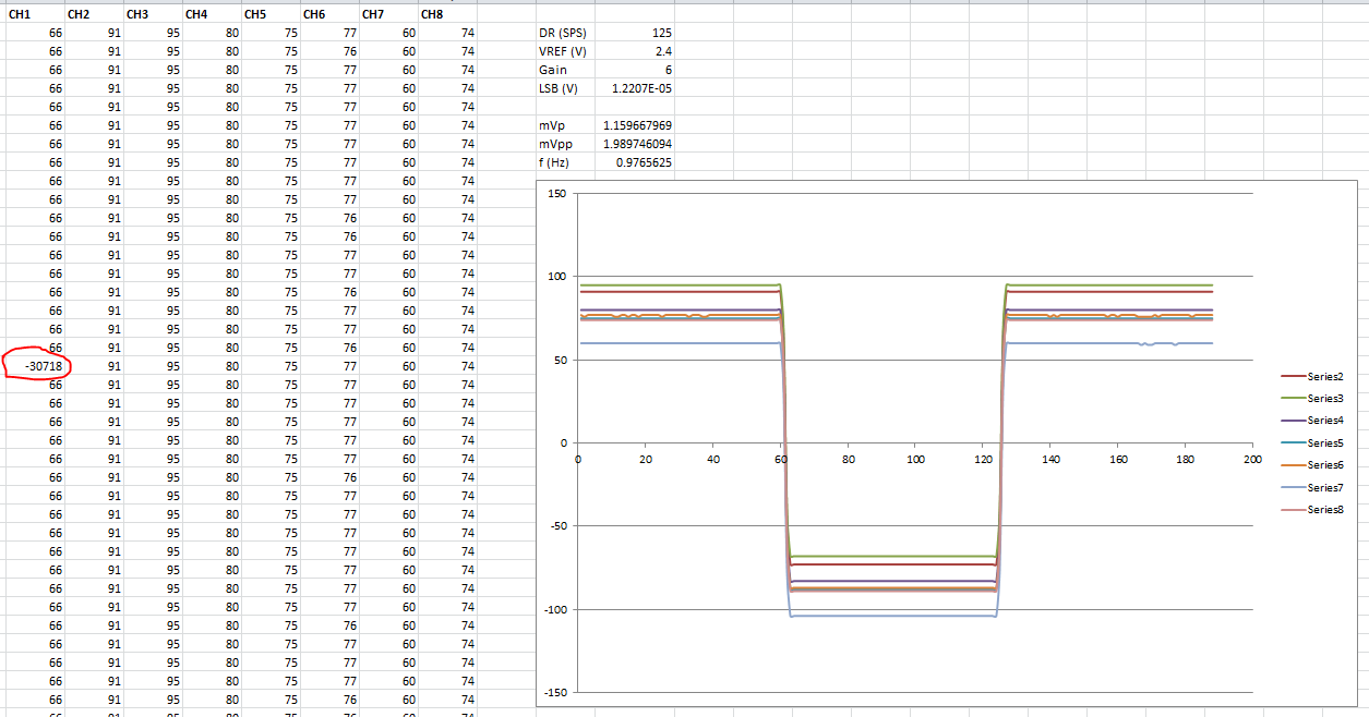
Here are require setting for getting test signal
output data rate =500sps
reference voltage=2.4v
gain setting =6
Config1=0xA6
config2=0x10
config3=0xC0
channelset=0x05
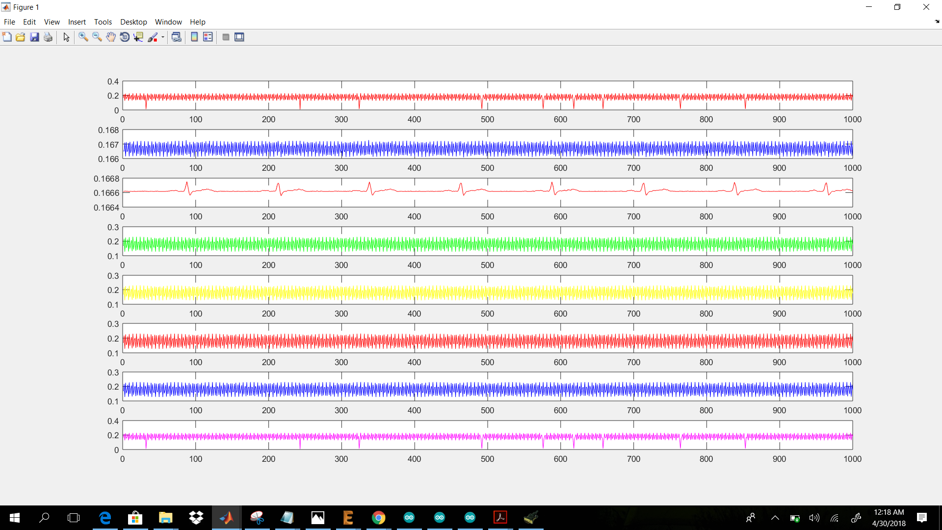
I have one another question about the electrode input, i connect ecg simulator skx2000c with inputs of ADS1198, and as simulator gives us filtered output so as i think so there is no need to add analog anti-aliasing filter at front end so i connect simulator output directly to the input of ADS1198 but the output seems very bad except channel 3.
As i posted earlier test signal for channel 2-7(except chan1 and chan8) seems good then what is the problem with electrode input, i change setting in config 3 mux setting to 000(Normal electrode input) but i donot set RLD and WCT because as i think WCT and RLD is not require for simulator filtered output as RLD remove common mode noise and WCT is reference for chest leads which simulator already generate.
now please tell me if i am wrong then what are the setting for RLD (8 channel) and WCT and any other register for Electrode input.
below is attachment of 8 Channel electrode output

thanks
Hello Ahmed,
Thanks for the registers settings. A couple comments about that:
Were you able to check your SPI transactions with a logic analyzer and verify the timing?
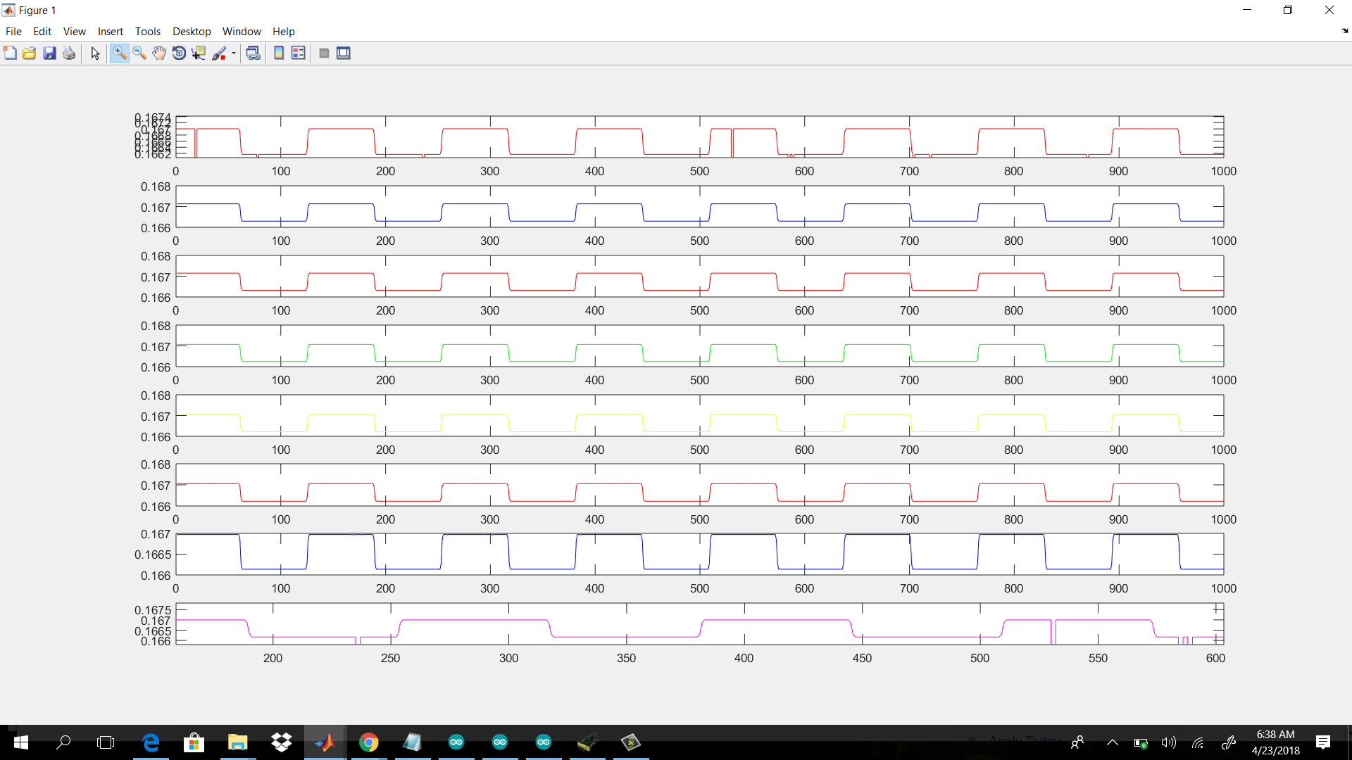
I've replotted your data after reversing the XOR function you had applied. The signal amplitude looks correct. The spikes you observed on CH1 are likely the cause of either misreading the data or data corrupt due to the overlap of data transfer with a new /DRDY interrupt.
Please begin a new thread to discuss your other question regarding your electrode input configuration.
Best Regards,