Part Number: ADS8556
Other Parts Discussed in Thread: ISO7241C
Hi team,
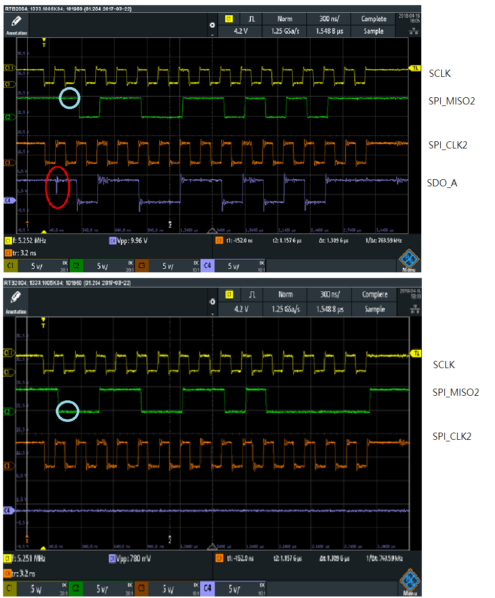
When CH_A0 input is -3V, there is a glitch in below waveform picture top side at SDO_A in red circle.
And when take out the test probe at SDO_A as below waveform picture bottom side, you can see SPI_MISO2 in blue circle is low but that should be high.
There is the same phenomenon as above when CH_A0 input is -1~ -5V but when input is such as -7V, there is no SPI_MISO2 data issue since the data is zero at that bit and no glitch at SDO_A.
Then doing a quick experiment by adding a 10pF(as a probe cap value) at SDO_A, then it shows as the waveform picture top side and that's correct.
May I know why there is a pulse? Is that caused by the ADS8556 itself?
And why need to add a 10pF at SDO_A to solve the issue?
Or by adding the 10pF is not correct and how to improve?
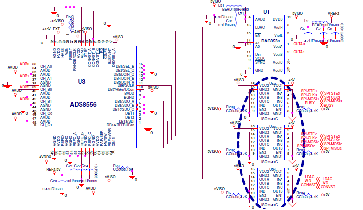
I also attached the schematic in below.
Thank you!