This thread has been locked.

If you have a related question, please click the "Ask a related question" button in the top right corner. The newly created question will be automatically linked to this question.

ADS1292R: ADS1292R RLD lead-off detection result in IN2N abnormity?

Part Number: ADS1292R

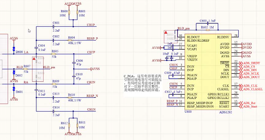
This is the schematic.

Our customer uses the RLD lead-off detection function of ADS1292R. When the electrodes fall off, It is mistakenly reported as IN2N falling. This phenomenon is not only present on their PCBA, but also in TI’s demonstration kit (ADS1X9XECG FE + Fluke ProSim 8 Vital Signs Patient Monitor Simulator).

Here are their test processes:

  1. Using ADS1X9XECG FE and ProSim 8, connect 3 electrodes : RA,LA,RL
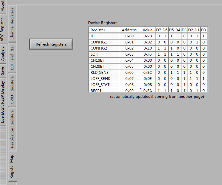
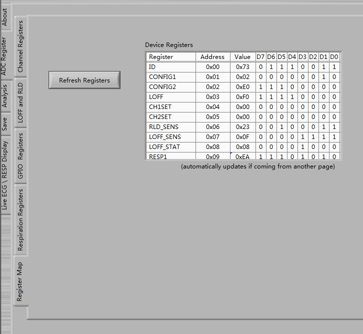
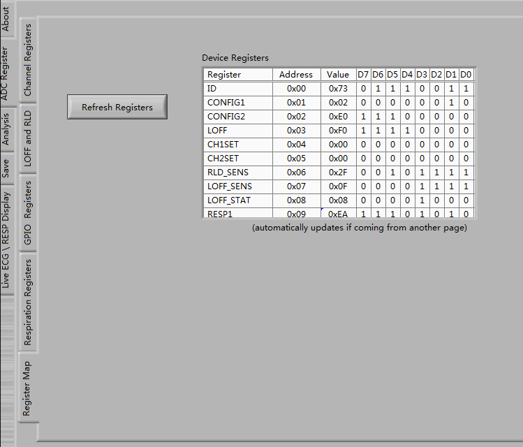
  2. Set the relevant registers at “LOFF and RLD” tab.
  3. Set four configurations at “register map” tab in turn.
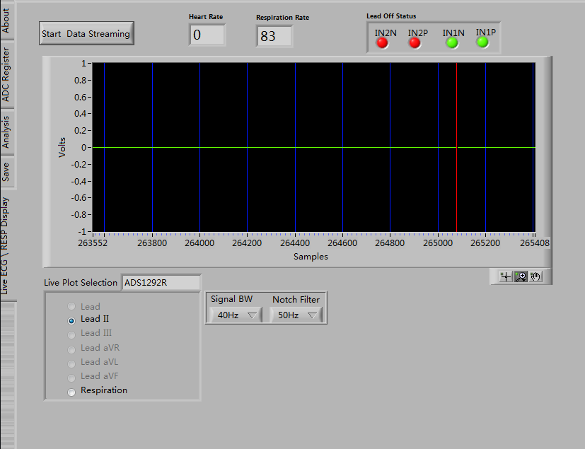
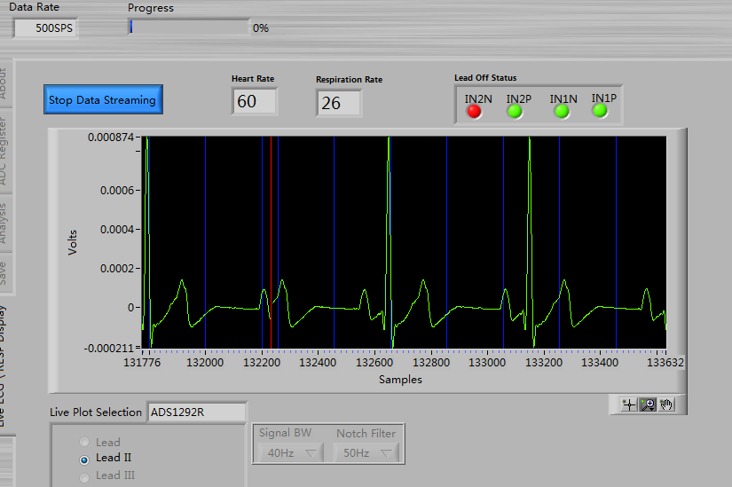
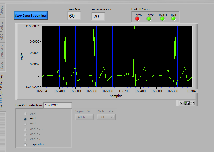
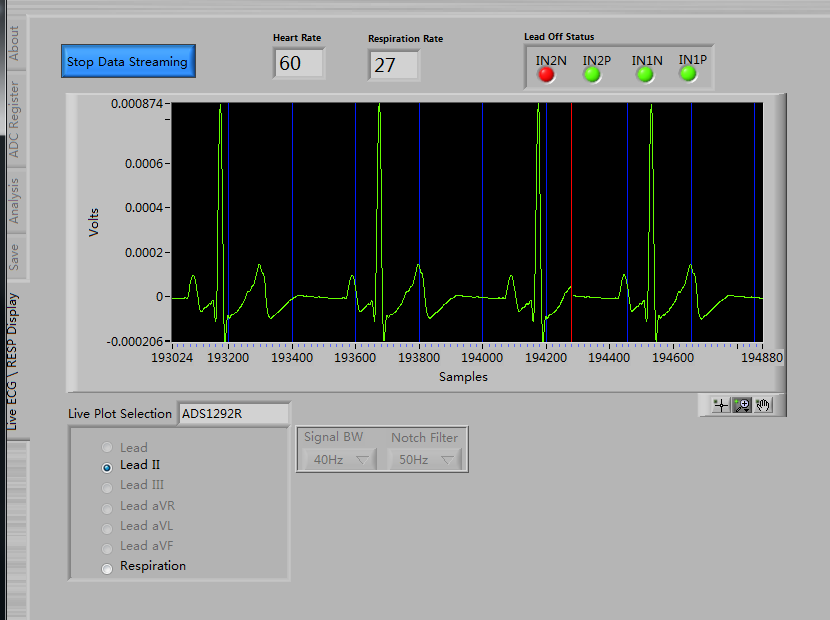
  4. Click “Live ECG” tab, and disconnect the RL electrode from the emulator. Wait about 1-2 minutes to observe the off status indicator.

Configuration1:

Phenomenon 1:

Configuration 2:

Phenomenon 2:

Configuration 3:

Phenomenon 3:

Configuration 4:

Phenomenon 4:

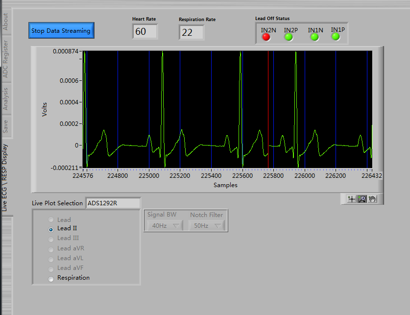
The above 4 kinds of configurations, will report IN2N fall off, in 1-2 minutes after the electrode was disconnected.

===================================================================

Phenomenon 5:

No abnormalities after disconnecting all electrodes.

  • Hi Morgan,

    Thanks for your post and welcome to our forum!

    First, let me point out that the RLD lead-off sense function is only useful when the RLD amplifier is powered-down. Otherwise, the RLD output will always be driven to mid-supply and the comparator will never detection a lead-off event for the RLD electrode. The RLD lead-off sense function should have no effect on the other electrodes and can be disabled for normal operation.

    The other changes you made to the RLD_SENS register (bits [3:0]) only control the connection of PGA outputs to the RLD amplifier inverting input for common-mode derivation. If one of the PGA inputs has railed (i.e. IN2P), then the corresponding PGA output (i.e. PGA2P) will also rail and may force the RLD output to change.

    What are your LOFF settings? Have you tried adjusting the lead-off current magnitude or comparator thresholds?

    Best Regards,