Because of the Thanksgiving holiday in the U.S., TI E2E™ design support forum responses may be delayed from November 25 through December 2. Thank you for your patience.

This thread has been locked.

If you have a related question, please click the "Ask a related question" button in the top right corner. The newly created question will be automatically linked to this question.

ADS1298: SPI Communication with MSP432

Part Number: ADS1298

Dear Sir,

I am using MSP432 to communicate with ADS1298R ECFE evaluation board. I am modifiying example code provided with SDK of MSP432. 

Connection on MSP432

P1.5 -> SCLK 

P2.3 -> Chip Select

P1.7 -> DIN

P1.6 -> DOUT

P2.4 -> DRDY

CLKSEL -> 1 

START and PWDN connected to 3.3 V power supply of MSP432 board.

I am using Internal clock of ADS1298. But every time i try to read register values either it gives 0x0 or some arbitrary values.

Process of reading register values, i am following:

First writing RESET command, followed by SDATAC command then any command like reading any Register value. But It is not giving as expected value.

Any suggestion might be helpful. Thanks in advance.

Regards

Anurag Tamboli

  • Hello Anurag,

    Thanks for your post and welcome to our forum!

    Before you configure any registers, do you see the /DRDY pin toggling at the default data rate of 500 SPS (measure the period between consecutive falling edges)?

    While the board is powered on, please probe the supply voltages, VCAP1, and VREFP to confirm they are correct.

    Best Regards,
  • Hello Ryan,

    I forgot to mention i am using ADS1298R ECGF evaluation kit which comes with MMB.

    I did as you instructed. When Board was powered from MSP-EXP432P launchpad ( I am only supplying 3.3v and 5V ).

    All supply voltages are okey except 1.8V which i didn't supply. (Checked power supply on TP7, TP8, TP5 , TP13, TP6, TP3 and TP9)

    VREP checked at JP3, it is zero.

    I don't know how to check VCAP1 on board.

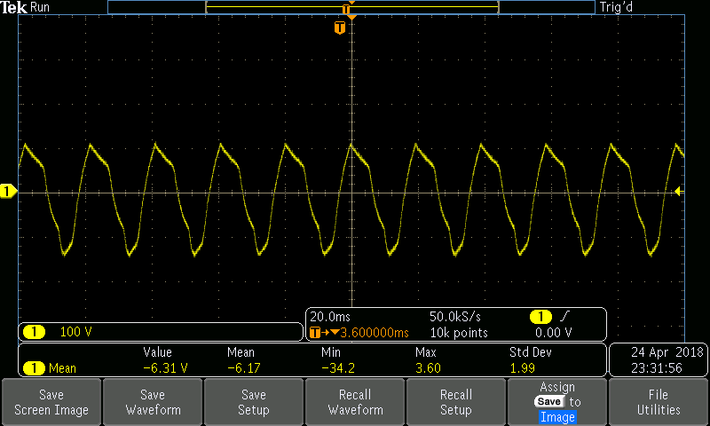
    At last, DRDY pin is toggling but not at 500SPS. Its coming 50SPS. (Attached photo for your reference)

    Regards

    Anurag Tamboli

  • Hello Anurag,

    /DRDY looks like it is showing 50-Hz power line interference, not the interrupt signal generated by the ADS1298R.

    VCAP1 is bypassed externally with a 22uF capacitor to GND (C9). You can probe across C9 to check it. If it is 0 V, then the ADS1298R is not powering up correctly. Please make sure you following the "Initial Flow at Power Up" diagram in Figure 93.

    Are you trying to use the MMB0 and MSP432 together, or do you only use the MSP432 LaunchPad? Please note that our EVM is not intended as an open source development tool.

    Best Regards,
  • Hello Ryan,

    Sorry for late reply. As you have mentioned that at DRDY pin i am getting 50 Hz noise. I did a little experiment.

    I have powered MMB through battery as suggested in User guide then i have observed DRDY again. 

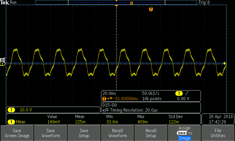
    DRDY still corrupted by 50 Hz noise (correct me if i am wrong). 

    As you have suggested to use power up sequence from ADS1298 Datasheet. I am able to read and modify all register.

    I am only using MSP432 as controlling microprocessor.

    Thank you for time. I really appreciate it.

    Regards

    Anurag Tamboli

  • Hello Anurag,

    The /DRDY pin does not appear to be functioning at all, which indicates that the device is not converting. The noise you see is likely coupling from a nearby light source.

    1. What is the status of the START pin on the ADS1298R? Is it high or low?
    2. Can you install JP23 as [1-2] and JP18 as [2-3] to select an external CLK source? Please probe JP18[2] to confirm the on-board clock is working properly.
    3. What is the value of the CONFIG4[3]? Are you in Continuous Conversion or Single-Shot Mode?

    Just a note - please adjust your oscilloscope probe to the correct voltage scale.

    If you are not using the MMB0 to communicate with the PC, then there is really no purpose to connecting the MMB0 and ADS1298RECGFE together. It may be easier to disconnect them and only connect the supplies you need directly to the daughterboard using separate jumper wires.  This would remove the possibility that the DSP on the MMB0 is still running some firmware and conflicting with your setup.

    Best Regards,

  • Hi Ryan,

    Sorry for late reply. I caught up with bluetooth configuration issue.

    So i removed all jumpers and connected them again as suggested in Datasheet. Apparently some jumper settings were wrong.

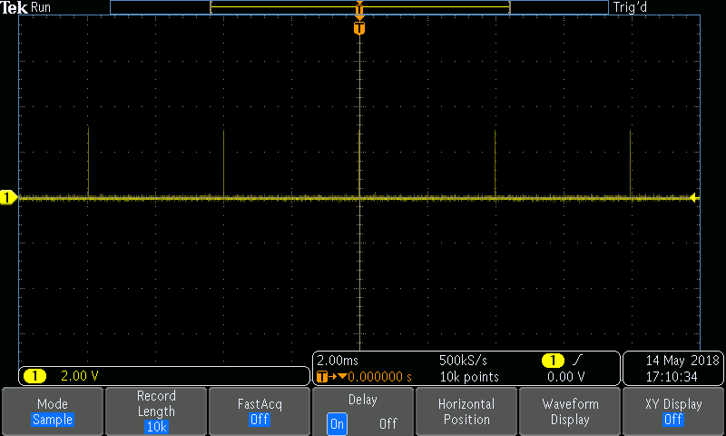
    I got DRDY Changing every 2ms (for 500 SPS).

    Last 2 question for this post. If you don't mind.

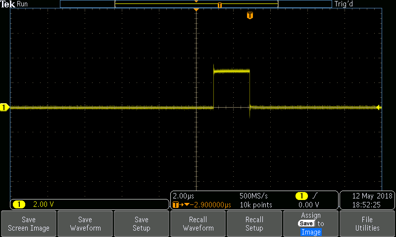
    First : when DRDY Pin goes high, it indicates data ready for transfer right?

    Second : if i miss data read for like one DRDY cycle then does it corrupt next cycle data?

    Thank you Ryan for your precious time. I really appreciate it.

    Regrads

    Anurag Tamboli