This thread has been locked.

If you have a related question, please click the "Ask a related question" button in the top right corner. The newly created question will be automatically linked to this question.

ADS1115: Inaccurate differential Measurement above VDD/11

Part Number: ADS1115

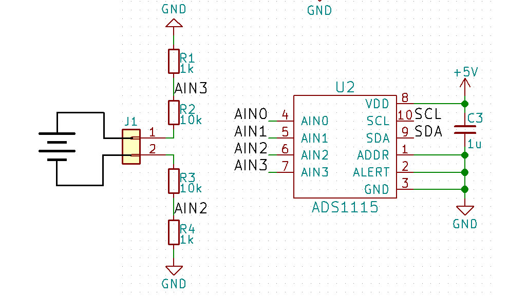
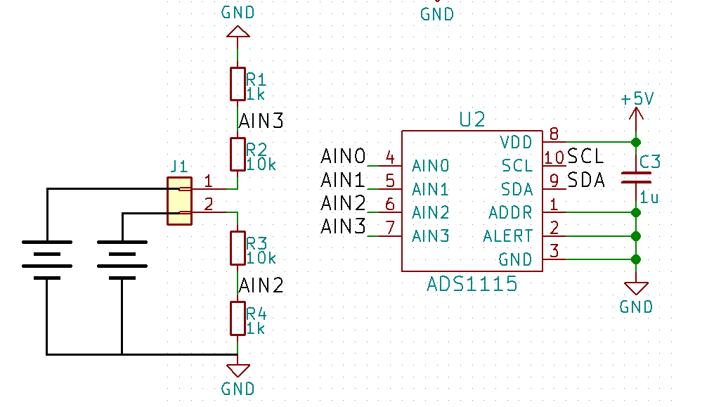
As seen in the Schematic, I'm using a 1k/10k Voltage Divider to increase the Input Range of the ADS1115.

This setup works accurately at up to 5V on J1.

Above 5V, the Device consistently reports Voltages below the actual Value.

This effect increases with Voltage, at 6V the Error is about 0.2V, at 10V the Error is already 1V.

Can somebody tell me why this happens and how to fix it?

  • Felix,


    I don't see anything unusual about your circuit. Voltage dividers can be used to lower the input voltage to within the input range of the ADC, so this should work. However, I do have a few questions about your setup.

    First, are you measuring from AIN2 to AIN3 or are you making two measurements, one from AIN2 to ground and another from AIN3 to ground? I also want to know how the device is configured and what is written into the configuration register. I'd like to make sure that the configuration register is correctly programmed, so I'd like you to read back from the device as well and confirm the register write completed.

    After that, is there any other circuitry on the front end of the ADC? What is the source voltage that you have attached to J1? Does the input voltage at J1 have a defined common mode input voltage? Are AIN0 and AIN1 left unconnected?

    You should also measure (with a multimeter) the voltage at J1 and then measure the voltages at AIN2 and AIN3 with respect to ground as well. To debug this, I would construct a table of inputs and outputs with the following: Voltage @ J1, Voltage @ AIN2, Voltage @ AIN3, ADC output (in code), ADC output converted to voltage.

    Take measurements from 0V to 10V input in 1V increments and check to see if the error is linear or if there is some non-linear behavior that changes at some point in the series. Again, the goal is to put in known input voltages and see how the error changes as the error changes. It might help in debugging the circuit.


    Joseph Wu
  • I'm measuring from AIN2 to AIN3 using the following Library.
    https://github.com/adafruit/Adafruit_ADS1X15

    For testing Purposes I'm using a Bench Power Supply with a 100Ohm Load between VCC and GND.
    The Voltage is measured in parralel by a Multimeter and the ADS1115, which are connected to either end of the Load.

    AIN0 and AIN1 are floating
    All that is connected to AIN2 and 3 is shown in the Image, there are other components on the digital Side though.
    (Namely an MCU and a 7 Segment Display)

    I will take the Measurements and post them later.

  • Felix,

    Do you have something like this:

    1.

    or something like this:

    2.

    In the first schematic, nothing defines the common mode input voltage. In this way, the value at AIN2 and AIN3 would depend on where the common mode input settles. In the second schematic, the supply measurement would give a reliable reading. The input voltage is the difference between the two divided by 11, and the common mode input is clearly defined. If you only have one supply, you could still make a measurement similar to the second circuit by tying one input to ground.

    In the first schematic, without the reference to a common ground, the measurement may not give a reading you expect.

    Joseph Wu

  • It works when I connect the two Grounds.

    I thought that differential measurement would not need a common Ground since the only the Difference is measured.
    But I guess since I'm using a Voltage Divider with reference to Ground, a Shift in Ground Potential skews the measurement.

    Knowing what I know now, a Setup like this would make more Sense:

    Can you confirm this?

    AIN3 should still be protected from Overvoltage because R3 Limits the Current so that the internal ESD Diodes are not overwhelmed.

  • Felix,


    I believe that's correct. With this new input setup, the input source and ADC now have a common ground. This would force the source into the input range of the ADC. Adding the series resistance to AIN3 shouldn't hurt the measurement.


    Joseph Wu