Tool/software: Linux
Hello,
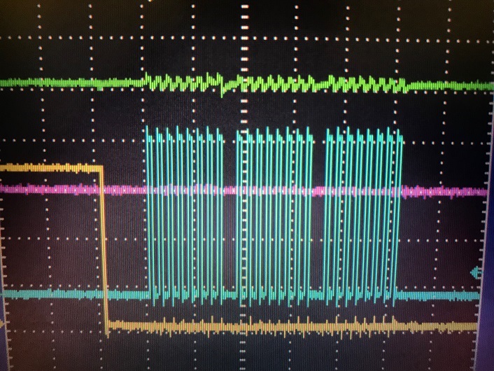
I'm trying to use an ADS7952 in Auto-1 mode with a Raspberry Pi Zero. I want to write the code in python but there isn't a lot of references out there for guidance. The first few iterations I've tried have not been successful in communicating with the ADS. Can someone review my files and tell me if I'm on the right track? I'm trying to use all 12 channels of the ADS and utilize the SPI bus.
Thanks in advance.
#import Adafruit_GPIO as GPIO
#import Adafruit_GPIO.SPI as SPI

class ADS7952(object):
    """Class to represent an ADS 7952 analog to digital onverter."""

    def __init__(self, clk=None, cs=None, miso=None, mosi=None, spi=None, gpio=None):

        """Initialize MAX31855 device with software SPI on the specified CLK, CS, and DO pins.  Alternatively can specify hardware SPI by sending an Adafruit_GPIO.SPI.SpiDev device in the spi parameter."""

        self._spi = None
        # Handle hardware SPI
        if spi is not None:
            self._spi = spi
        elif clk is not None and cs is not None and miso is not None and mosi is not None:
            # Default to platform GPIO if not provided.
            if gpio is None:
                gpio = GPIO.get_platform_gpio()
                self._spi = SPI.BitBang(gpio, clk, mosi, miso, cs)
        else:
            raise ValueError('Must specify either spi for for hardware SPI or clk, cs, miso, and mosi for softwrare SPI!')
                # Set SPI clock in Hz
        self._spi.set_clock_hz(500000)
        self._spi.set_mode(0)
        self._spi.set_bit_order(SPI.MSBFIRST)

    def read_adc(self, adc_number):
        """Read the current value of the specified ADC channel (0-11).  The values can range from 0 to 4095 (12-bits)."""

        # Setting Auto-1 mode
        command = 0b0100000000000001
        resp = self._spi.transfer([command, 0x0, 0x0])  #send to SPI bus
        command = 0b1001001011000000
        resp = self._spi.transfer([command, 0x0, 0x0])
        command = 0b0010110000010001                    #set Auto-1 mode
        resp = self._spi.transfer([command, 0x0, 0x0])
        assert 0 <= adc_number <= 11, 'ADC number must be a value of 0-11!'
        command = 0b0000000000000000                    #remain in Auto-1 mode
        resp = self._spi.transfer([command, 0x0, 0x0])

        # Parse out the 12 bits of response data and return it.
        result = (resp[0] & 0x01) << 11
        result |= resp[1] >> 3
        result |= resp[2] >> 5
        return (result & 0x0FFF)
#import time
import os
import time
from time import sleep
from datetime import datetime

# Import SPI library (for hardware SPI) and RAS library.
import Adafruit_GPIO.SPI as SPI
import RAS_ADS7952

# Hardware SPI configuration:
SPI_PORT   = 0
SPI_DEVICE = 0
mcp = RAS_ADS7952.ADS7952(spi=SPI.SpiDev(SPI_PORT, SPI_DEVICE))

# Create a save file when software is initiated and stored in home/pi directory:
file = open("/home/pi/RAS_data_log.csv", "a")
i=0
if os.stat("/home/pi/RAS_data_log.csv").st_size == 0:
    file.write("Date and Time,Sensor1,Sensor2,Sensor3,Sensor4,Sensor5,Sensor6,Sensor7,Sensor8,Sensor9,Sensor10,Sensor11,Sensor12\n")

print('Reading ADS7952 values, press Ctrl-C to quit...')
# Print nice channel column headers.
print('| Date and Time | {0:>4} | {1:>4} | {2:>4} | {3:>4} | {4:>4} | {5:>4} | {6:>4} | {7:>4} | {8:>4} | {9:>4} | {10:>4} | {11:>4} |'.format(*range(12)))
print('-' * 57)
# Main program loop.
while True:
    # Read all the ADC channel values in a list.
    values = [0]*12
    for i in range(12):
        # The read_adc function will get the value of the specified channel (0-11).
        values[i] = mcp.read_adc(i)
        now = datetime.now()
    # Print the ADC values.
    print('| {0:>4} | {1:>4} | {2:>4} | {3:>4} | {4:>4} | {5:>4} | {6:>4} | {7:>4} | {8:>4} | {9:>4} | {10:>4} | {11:>4} |'.format(*values))
    file.write(str(now)+","+str(values)+"\n")
    file.flush()
    # Sample time in seconds...
    time.sleep(0.005)


